18
MV-700HR
8 Gamma 1
Procedure:
1. In the “7 B-ch Sub Contrast” status, connect the oscilloscope
to the TP907 and TP929 (GND) on the MONITOR board.
2. Press the [SOURCE] button to display “Gamma 1”.
3. Adjust by pressing the [VOLUME +]/[VOLUME --] buttons so
that the B value of waveform (fig. 8-2) becomes 2.1 V ±0.15
V.
9 Gamma 2
Procedure:
1. In the “8 Gamma 1” status, press the [SOURCE] button to
display “Gamma 2”.
2. Adjust by pressing the [VOLUME +]/[VOLUME --] buttons so
that the C value of waveform (fig. 8-2) becomes 3.6 V ±0.15
V.
q; VCO Free Run
Setting:
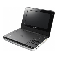
Procedure:
1. In the “9 Gamma 2” status, connect a frequency counter to
the TP711 and TP716 (GND) on the MONITOR board.
2. Press the [SOURCE] button to display “VCO Free Run”.
3. Adjust by pressing the [VOLUME +]/[VOLUME --] buttons so
that the value of frequency counter becomes 15.734 kHz ±50
Hz.
4. Confirm that the displayed screen is normally display.
+
–
frequency counte
MONITOR board
TP711
TP716 (GND)
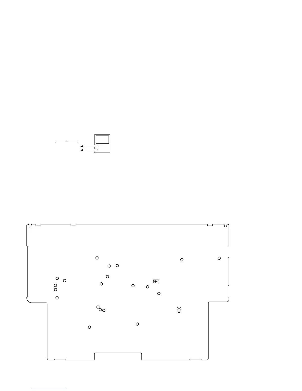
Adjustment Location:
qa Vertical Position
Procedure:
1. In the “q; VCO Free Run” status, input the monoscope signal
to the A/V INPUT jack (J1004 on the MAIN board).
2. Press the [SOURCE] button to display “PLL/V Pos”.
3. Adjust by pressing the [VOLUME +]/[VOLUME --] buttons so
that the vertical position of screen on the monitor becomes
the most suitable.
qs Horizontal Position
Procedure:
1. In the “qa Ve rtical Position” status, press the [SOURCE] button
to display “H Pos”.
2. Adjust by pressing the [VOLUME +]/[VOLUME --] buttons so
that the horizontal position of screen on the monitor becomes
the most suitable.
3. Press the [S-MENU] button to select the “EXIT”, and press the
[SOURCE] button to return to the “TEST MODE MENU”
screen.
TP751
TP753 (GND)
TP716 (GND)
TP503 (L)
TP504 (R)
TP505 (GND)
TP502
(R)
TP501 (L)
TP929 (GND)
TP908
TP907
TP906
TP917
TP711
TP801
TP802
TP388 (GND)
TP434
TP701
TP703 (GND)
RV851
RV801
– MONITOR BOARD (Component Side) –
 Loading...