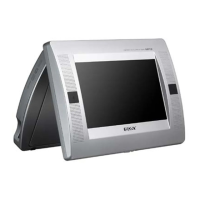
MAIN BOARD IC101 CXD9804R (RF AMP, SERVO DSP, MPEG DECODER)
Pin No.
DVDA I AC coupled input path A
DVDB I AC coupled input path B
DVDC I AC coupled input path C
DVDD I AC coupled input path D
DVDRFIP I AC coupled DVD RF signal input terminal
DVDRFIN I AC coupled DVD RF signal input terminal
MA I DC coupled main-beam RF signal input A
MB I DC coupled main-beam RF signal input B
MC I DC coupled main-beam RF signal input C
MD I DC coupled main-beam RF signal input D
SA I Focus error signal input terminal
SB I Focus error signal input terminal
SC I DC coupled sub-beam RF signal input C Not used
SD I DC coupled sub-beam RF signal input D Not used
CDFON I CD focusing error negative input terminal
CDFOP I CD focusing error positive input terminal
TNI I 3 beam satellite PD signal negative input terminal
TPI I 3 beam satellite PD signal positive input terminal
MDI1, MDI2 I Laser power monitor input terminal
LDO2 O Laser diode drive signal output terminal (for DVD)
LDO1 O Laser diode drive signal output terminal (for CD)
SVDD3 - Power supply terminal (+3.3V)
CSO/RFOP O Central servo signal output or positive main beam summing output terminal
RFLVL/RFON O RFRP low pass or positive main beam summing output terminal
V2REFO O Reference voltage (+2.8V) output terminal
V20 O Reference voltage (+2V) output terminal
VREFO O Reference voltage (+1.4V) output terminal
FEO O Focus error monitor output terminal
TEO O tracking error monitor output terminal
TEZISLV O Slice level of tracking error signal output terminal
OP_OUT O Output from the internal OP AMP
OP_INN I Input to the internal OP AMP Not used
OP_INP I Input to the internal OP AMP Not used
DMO O Spindle motor control signal output terminal
FMO O Sled motor control signal output terminal
TROPENPWM O Disc tray motor control signal output terminal Not used
PWMOUT1 O PWM output terminal Not used
TRO O Tracking coil control signal output terminal
FOO O Focus coil control signal output terminal
USB_VSS - Ground terminal
USBP I/O USB communication data input/output terminal Not used
USBM I/O USB communication data input/output terminal Not used
USB_VDD3 - Power supply terminal (+3.3V)
FG I Motor hall sensor input terminal
• IC Pin Function Description
 Loading...