Parts Identifications
17
Overview
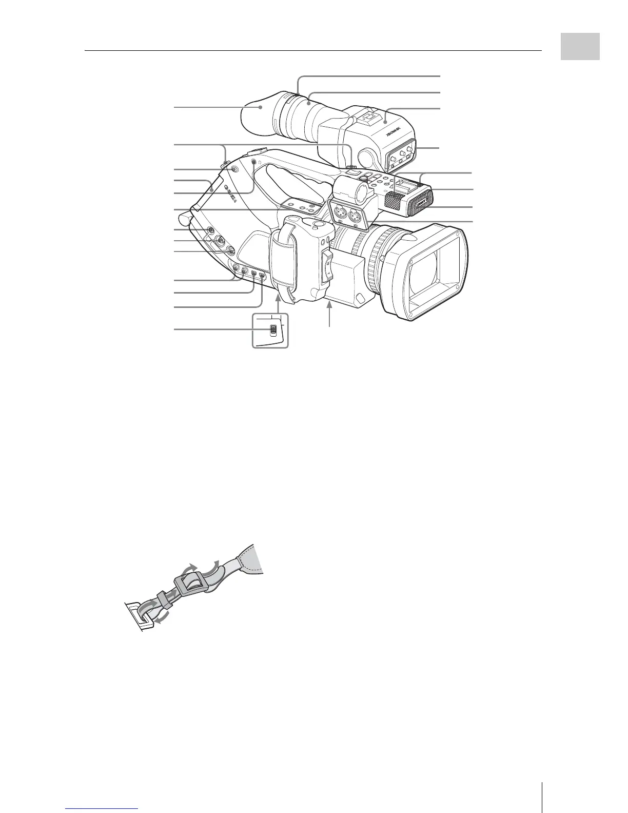
13. Eyecup
The eyecup can be attached in the reversed
direction.
To reattach the eyecup, stretch it a little to
attach to the viewfinder and fit the rim of the
eyecup into the groove of the viewfinder.
14. Hooks for the shoulder strap (left and
right)
Attach the supplied shoulder strap as shown
below.
15. BATTERY RELEASE button (page 26)
16. Battery pack receptacle (page 26)
17. Headphone jack (stereo mini jack) (pa
ge
69, page 96)
18. DC IN (DC power input) connector (pa
ge
27)
19. MONITOR OUT connector (BNC type)
(pag
e 129)
20. S VIDEO connector (4-pin) (page 129)
21. AUDIO OUT CH-1/CH-2 connectors
(RCA phono) (page 129)
22. COMPONENT OUT connector (Mini D)
(page 129)
23. USB connector (Mini B) (page 130)
24. Lens mount stopper switch (page 34)
25. Eyepiece focusing knob (page 30)
26. Eyepiece (page 32)
27. Viewfinder (page 30)
28. Built-in microphones (page 67)
29. REC/TALLY lamp (page 48, page 148)
30. IR remote control receptor
31. AUDIO IN CH-1/CH-2 connectors (XLR)
and input selection switches (page 67)
MIRR
OR IM
AG
E
O
FF ON
DISPL
AY/BA
TT
INFO
Z
EB
RA
PE
AK
IN
G
C
O
NT
RA
ST
BR
IG
H
T
LOCK
RELEASE
B
AT
T
E
R
Y
R
E
LE
A
S
E
COMPONENT
OUT
D
C
IN
M
O
N
ITO
R
O
UT
S
VID
E
O
AUDIO OUT
CH
-1
CH
-2
A
S
H
OT
TR
A
NS
I
TIO
N
B
T
C/U
-B
IT
/DU
R
A
TIO
N
TH
UMN
AIL
F REV
PR
EV
SEL/SET
P
LA
Y
/P
AU
S
E
S
TOP
CA
NCE
L
R
L
F FWD
NE
XT
RE
C
START/ST
OP
H
OLD
l
sL
j
G
/
S
J
MONITOR
VOL
H
L
OFF
EXPANDED
FOCUS
REC
REVIEW
RELEASE
START/
STOP
A
U
D
IO
IN
CH-1
MIC
LINE
M
IC+48V
MIC
LINE
MIC+48V
CH-2
LOCK
RELEASE
13
14
15
16
17
18
19
20
21
22
23
24
27
29
28
30
31
26
25
Bottom (page 20)
Upper operation
panel (page 19)
Viewfinder control
panel
(page 20)
Connectors 18 to 20 have indivial caps, and 21 to 23 are behind a shared cover.
1
2
3
4