1-19
17
Hookups
B If you are connecting to an S VIDEO input jack
Connect an S VIDEO cord (not supplied). You will enjoy high quality images.
C If you are connecting to a monitor, projector, or AV amplifier (receiver)
having component video input jacks (Y, P
B, PR)
Connect the component via the COMPONENT VIDEO OUT jacks using a component video
cord (not supplied) or three video cords (not supplied) of the same kind and length. You will
enjoy accurate color reproduction and high quality images. If your TV accepts progressive
(480p) format signals, you must use this connection and then press PROGRESSIVE on the front
panel to accept progressive video signals. The PROGRESSIVE indicator lights up in blue when
the player outputs progressive signals. See “Using the PROGRESSIVE button” on the next page
for more information.
When connecting to a wide screen TV
Depending on the disc, the image may not fit your TV screen. If you want to change the aspect
ratio, please refer to page 60.
Notes
• Do not connect the player to a VCR. If you pass the player signals via the VCR, you may not receive a clear
image on the TV screen.
• Consumers should note that not all high definition television sets are fully compatible with this product and
may cause artifacts to be displayed in the picture. In the case of 480 progressive scan picture problems, it
is recommended that you switch the connection to the standard definition output. If there are questions
regarding your Sony TV set’s compatibility with this model 480p DVD player, please contact our customer
service center.
Green
Blue
Red
Green
Blue
Red
VCR
CD/DVD player
TV
Connect
directly
18
Using the PROGRESSIVE button
You can fine-tune the Progressive 480p video signal output when you press PROGRESSIVE on
the front panel (the PROGRESSIVE indicator lights up in blue) and connect the player using the
COMPONENT VIDEO OUT jacks to a TV that is able to accept the video signal in progressive
format.
◆ Conversion Modes
DVD software can be divided into two types: film based software and video based software.
Video based software is derived from the TV, such as dramas and sit-coms, and displays images
at 30 frames/60 fields per second. Film based software is derived from film and displays images
at 24 frames per second. Some DVD software contains both Video and Film.
In order for these images to appear natural on your screen when output in PROGRESSIVE mode
(60 frames per second), the progressive video signal needs to be converted to match the type of
DVD software that you are watching.
Press PROGRESSIVE repeatedly to turn or change the displays as follows:
* Appears as NORMAL, P AUTO, P VIDEO, or P FILM on the front panel display
• NORMAL (INTERLACE)
Select this when you are connected to a standard (Interlace format) TV.
• PROGRESSIVE AUTO
Select this when you are connected to a progressive TV. This will automatically detect if you
are playing Film based or Video based software and convert the signal to the appropriate
conversion mode. Normally select this position when you are connected to a progressive TV.
• PROGRESSIVE VIDEO
Select this when you are connected to a progressive TV. This will set the conversion mode for
Video based software, regardless of the type of software that you are playing.
• PROGRESSIVE FILM
Select this when you are connected to a progressive TV. This will set the conversion mode for
Film based software, regardless of the type of software that you are playing.
Notes
• When you select PROGRESSIVE FILM, the progressive format images may become unclear or unnatural.
If this happens, select PROGRESSIVE VIDEO.
• When you play video based software with progressive signals, sections of some types of images may appear
unnatural due to the conversion process when output through the COMPONENT VIDEO OUT jacks.
Images from the S VIDEO OUT and LINE OUT (VIDEO) jacks are unaffected as they are output in the
normal (interlace) format.
NORMAL (INTERLACE)*
PROGRESSIVE AUTO*
PROGRESSIVE VIDEO*
PROGRESSIVE FILM*
19
Hookups
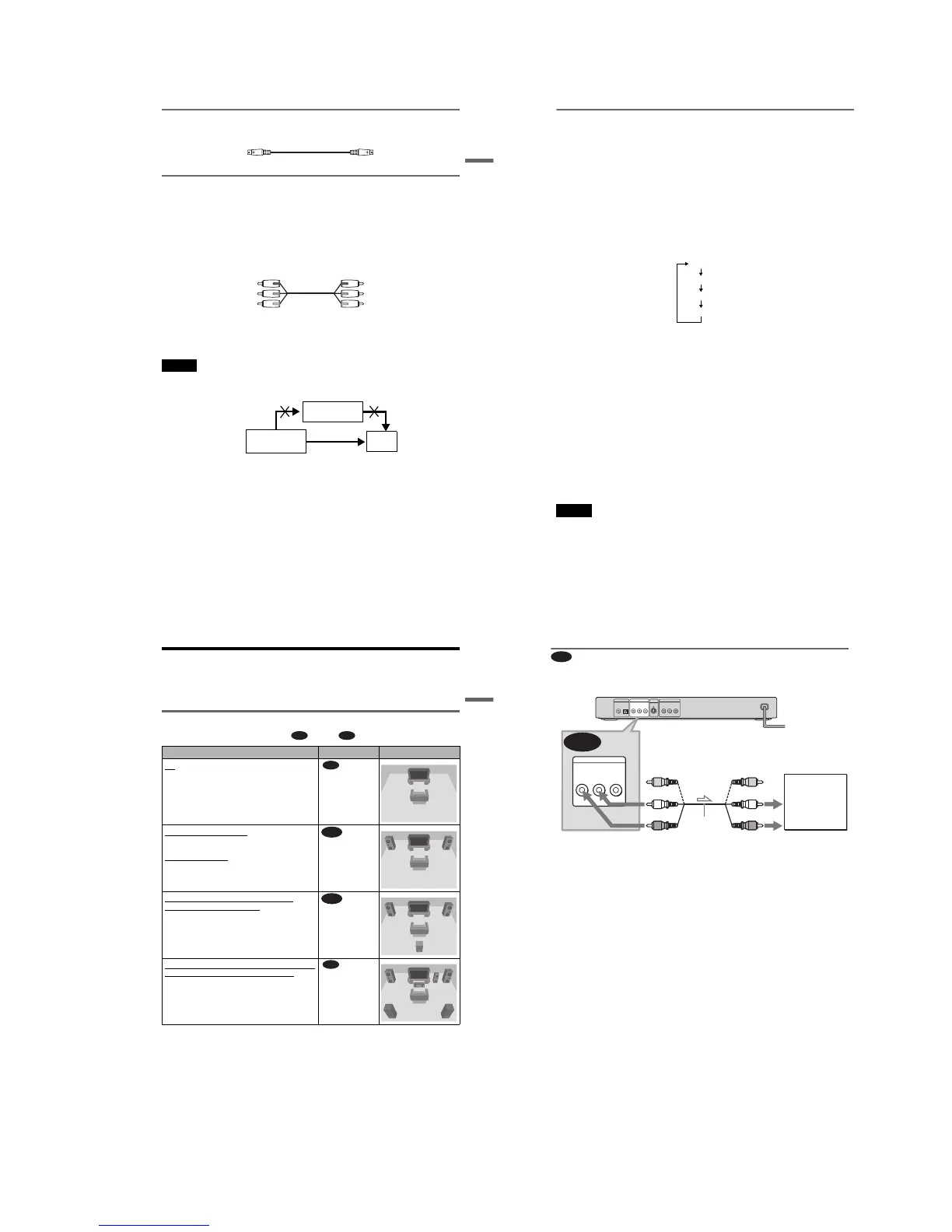
Step 4: Connecting the Audio Cords
Refer to the chart below to select the connection that best suits your system. Be sure to also read
the instructions for the components you wish to connect.
Select a connection
Select one of the following connections, through .
* Manufactured under license from Dolby
Laboratories. “Dolby,” “Pro Logic,” and the
double-D symbol are trademarks of Dolby
Laboratories.
** “DTS” and “DTS Digital Out” are trademarks
of Digital Theater Systems, Inc.
Components to be connected Connection Your setup (example)
TV
• Surround effects: TVS DYNAMIC (page 46),
TVS WIDE (page 46)
(page 20)
Stereo amplifier (receiver)
and two speakers
• Surround effects: TVS STANDARD (page 46)
or
MD deck/DAT deck
• Surround effects: TVS STANDARD (page 46).
(page 21)
AV amplifier (receiver) having a Dolby
*
Surround (Pro Logic) decoder and 3 to 6
speakers
• Surround effects: Dolby Surround (Pro Logic)
(page 67)
(page 22)
AV amplifier (receiver) with digital input jacks
having a Dolby Digital or DTS** decoder and 6
speakers
• Surround effects:
– Dolby Digital (5.1ch) (page 67)
– DTS (5.1ch) (page 67)
(page 23)
A D
A
B
C
D
,continued
20
Connecting to your TV
This connection will use your TV speakers for sound.
* The yellow plug is used for video signals (page
16).
z Hint
When connecting to a monaural TV, use a stereo-
mono conversion cord (not supplied). Connect the
LINE OUT L/R (AUDIO) jacks to the TV’s audio
input jack.
A
A
PCM/DTS/
DOLBY DIGITAL
COAXIAL
OPTICAL
DIGITAL OUT
LINE OUT
S VIDEO
OUT
R-AUDIO-L
VIDEO
P
R
Y
COMPONENT VIDEO OUT
P
B
LINE OUT
R-AUDIO-L
VIDEO
TV
l : Signal flow
(white)
(red)
Audio/video
cord (supplied)
to audio input
(yellow)*
(white)
(red)
(yellow)*
to LINE OUT L/R
(AUDIO)
CD/DVD player