– 2 –
SAFETY-RELATED COMPONENT WARNING !!
COMPONENTS IDENTIFIED BY MARK ! OR DOTTED LINE
WITH MARK ! ON THE SCHEMATIC DIAGRAMS AND IN
THE PARTS LIST ARE CRITICAL TO SAFE OPERATION.
REPLACE THESE COMPONENTS WITH SONY PARTS
WHOSE PART NUMBERS APPEAR AS SHOWN IN THIS
MANUAL OR IN SUPPLEMENTS PUBLISHED BY SONY.
Notes on chip component replacement
• Never reuse a disconnected chip component.
• Notice that the minus side of a tantalum capacitor may be
damaged by heat.
TABLE OF CONTENTS
1. SERVICING NOTE .......................................................... 3
2. GENERAL .......................................................................... 4
3. DIAGRAMS
3-1. Circuit Boards Location ........................................................ 5
3-2. Block Diagrams
• Main Section....................................................................... 7
• Power Section ..................................................................... 9
3-3. Schematic Diagram – Video Input Section – ...................... 13
3-4. Printed Wiring Board – Video Input Section – ................... 15
3-5. Schematic Diagram – Input Section – ................................ 17
3-6. Printed Wiring Board – Input Section – .............................. 19
3-7. Schematic Diagram – S-Video Section – ............................ 21
3-8. Printed Wiring Board – S-Video Section – ......................... 23
3-9. Schematic Diagram – Speaker Section – ............................ 25
3-10. Printed Wiring Board – Speaker Section –...................... 27
3-11. Printed Wiring Board – Display Section – ....................... 29
3-12. Schematic Diagram – Display Section – ......................... 31
3-13. Schematic Diagram – Front Panel Section – ................... 33
3-14. Printed Wiring Board – Front Panel Section – ................. 35
3-15. Schematic Diagram – Power AMP Section –.................. 37
3-16. Printed Wiring Board – Power AMP Section – ................ 39
3-17. Schematic Diagram – Trans Section – ............................ 41
3-18. Printed Wiring Board – Trans Section – ........................... 42
3-19. IC Block Diagrams ........................................................... 43
3-20. IC Pin Functions ............................................................... 46
4. EXPLODED VIEWS
4-1. Case and Back Panel Section.............................................. 48
4-2. Front Panel Section ............................................................. 49
4-3. Chassis Section ................................................................... 50
5. ELECTRICAL PARTS LIST ........................................ 51
Parts No.
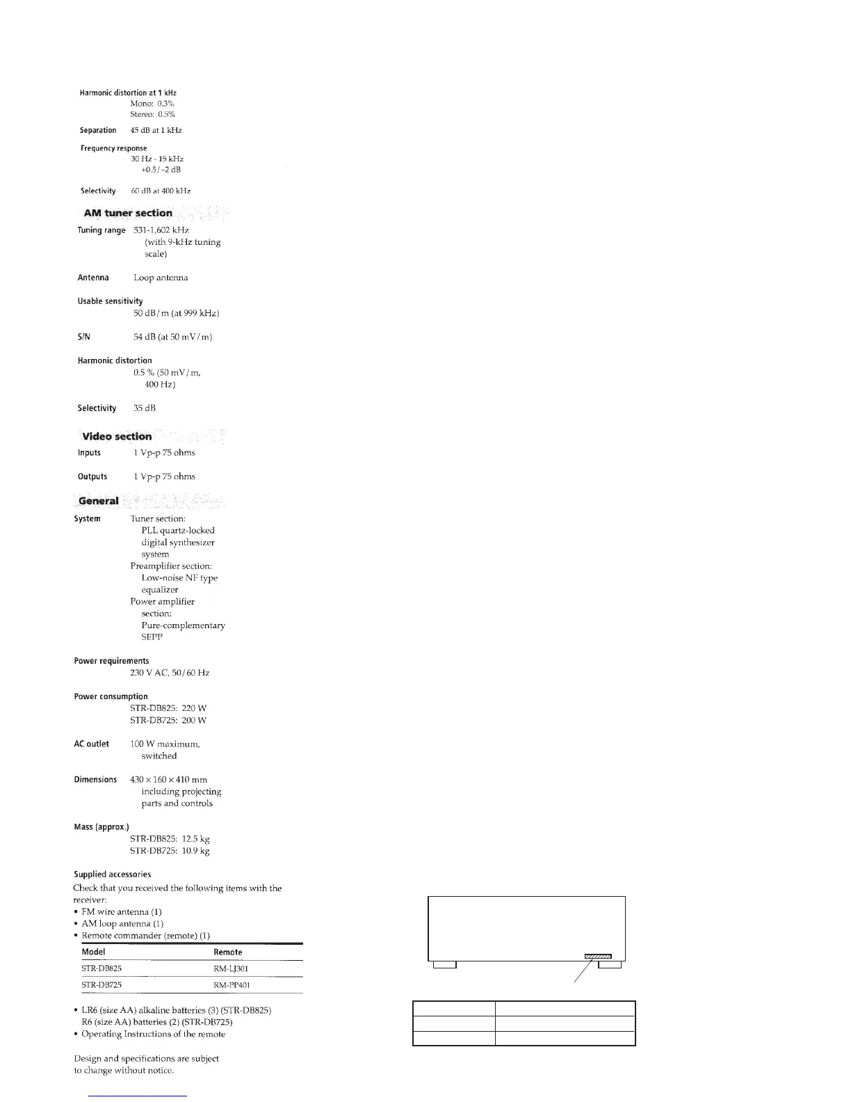
PARTS No. MODEL
MODEL IDENTIFICATION
— BACK PANEL —
4-900-493-0π
4-900-493-1π
DB725
DB825