EasyManua.ls Logo

Sony STR-DB795 Service Manual

Sony STR-DB795
98 pages
To Next Page IconTo Next Page
Page #1 background imageLoading...
Page #1 background image
SERVICE MANUAL
FM STEREO FM/AM PECEIVER
AEP Model
UK Model
E Model
Australian Model
SPECIFICATIONS
STR-DB795
Ver 1.0 2004.10
9-879-195-01
2004J05-1
© 2004.10
Sony Corporation
Audio Group
Published by Sony Engineering Corporation
This receiver incorporates Dolby* Digital and Pro
Logic Surround and the DTS** Digital Surround
System.
* Manufactured under license from Dolby
Laboratories.
“Dolby”, “Pro Logic” and the double-D symbol are
trademarks of Dolby Laboratories.
**“DTS” and “DTS Digital Surround” are registered
trademarks of Digital Theater Systems, Inc.
– Continued on next page –
Amplifier section
POWER OUTPUT
Models of area code AEP, UK, TW, KR, AUS
Rated Power Output at Stereo Mode
(8 ohms 1 kHz, THD 0.7%)
100 W + 100 W
2)
90 W + 90 W
3)
Reference Power Output
2)
(8 ohms 20 Hz20 kHz, THD 0.09%)
FRONT
1)
: 90 W + 90 W
CENTER
1)
: 90 W
SURR
1)
: 90 W + 90 W
SURR BACK
1)
: 90 W +
90 W
(8 ohms 1 kHz, THD 0.7%)
FRONT
1)
: 100 W + 100 W
CENTER
1)
: 100 W
SURR
1)
: 100 W + 100 W
SURR BACK
1)
: 100 W +
100 W
(8 ohms 1 kHz, THD 10%)
FRONT
1)
: 110 W + 110 W
CENTER
1)
: 110 W
SURR
1)
: 110 W + 110 W
SURR BACK
1)
: 110 W +
110 W
Models of area code SP, MY
Rated Power Output at Stereo Mode
(8 ohms 1 kHz, THD 0.7%)
90 W + 90 W
2)
Reference Power Output
2)
(8 ohms 1 kHz, THD 0.7%)
FRONT
1)
: 90 W + 90 W
CENTER
1)
: 90 W
SURR
1)
: 90 W + 90 W
SURR BACK
1)
: 90 W +
90 W
1) Depending on the sound field settings and the
source, there may be no sound output.
2) Measured under the following conditions:
3) Measured under the following conditions:
Area code Power requirements
AEP, UK, SP, MY, KR 230 V AC, 50 Hz
AUS 240 V AC, 50 Hz
TW 110 V AC, 60 Hz
Area code Power requirements
KR 220 V AC, 50 Hz
Frequency response
Inputs (Analog)
PHONO RIAA equalization curve
±0.5 dB
MULTI CH IN, SA-CD/
CD, MD/TAPE, DVD,
TV/SAT, VIDEO 1, 2, 3
10 Hz 100 kHz
+0.5/2 dB (when
ANALOG DIRECT is
selected)
PHONO Sensitivity: 2.5 mV
Impedance: 50 kilohms
S/N
3)
: 86 dB
(A, 2.5 mV
4)
)
MULTI CH IN, SA-CD/
CD, MD/TAPE, DVD,
TV/SAT, VIDEO 1, 2, 3
Sensitivity: 150 mV
Impedance: 50 kilohms
S/N
4)
: 96 dB
(A, 150 mV
5)
)

Table of Contents

Other manuals for Sony STR-DB795

Question and Answer IconNeed help?

Do you have a question about the Sony STR-DB795 and is the answer not in the manual?

Sony STR-DB795 Specifications

General IconGeneral
Dimensions (WxDxH)430 x 401 x 161 mm
Power requirements230V, 50/60Hz
Supported radio bandsFM, MW
Radio Data System (RDS)Yes
I/O ports5.1 Analogue Input - 1.0 Audio Input - 3.0 Audio Input Front - 1 AV, S-Video Audio Output - 1.0 Control A1 / A1 II Digital Input: coaxial - 1.0 Digital Input: optical - 4.0 Digital Output: optical - 1.0 Headphone Output Monitor Output (Picture): FBAS - 1.0 Monitor Output (Picture): S-Video - 1.0 Phono Input Speaker Selector A S-Video Input - 4.0 S-Video Output - 1.0 Video Input - 5.0 Video Output - 2.0
Connectivity technologyWired
Frequency range20 - 20000 Hz
Power consumption (standby)0.5 W
Power consumption (typical)290 W
Weight and Dimensions IconWeight and Dimensions
Weight12500 g

Summary

Servicing Notes

Unleaded Solder and Lead-Free Mark

Details unleaded solder characteristics and lead-free mark identification.

General Information

Main Unit and Remote Commander Overview

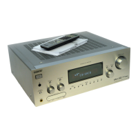
Describes main unit controls and remote commander functions.

Disassembly Procedures

Disassembly Flowchart

Provides a step-by-step visual guide for disassembling the unit.

Test Modes

Various Test Modes Description

Explains diagnostic modes like Factory Preset, AM Step Change, Sound Field Clear.

Electrical Adjustments

Bias Adjustment Procedure

Details the process for adjusting bias voltage for optimal performance.

Diagrams

Block Diagrams Overview

Illustrates functional blocks of tuner, video, and audio signal paths.

Printed Wiring Boards (PWBs) Layout

Shows physical component layout on boards like DIGITAL, MAIN, etc.

Schematic Diagrams Details

Provides detailed circuit schematics for DIGITAL, VIDEO, and MAIN sections.

Exploded Views

Case Section Exploded View

Illustrates external case components and their assembly.

Electrical Parts List

Component Categories and Board Listings

Lists parts like capacitors, resistors, transistors, and board assemblies with part numbers.

Related product manuals