Getting Started
masterpage:Right
lename[E:\SEM_Janet\Revision
ata\J9051275_2598516131DB798CEL\2598516131\GB03CON_STR-DB798-CEL.fm]
5
GB
model name1[STR-DB798]
[2-598-516-13(1)]
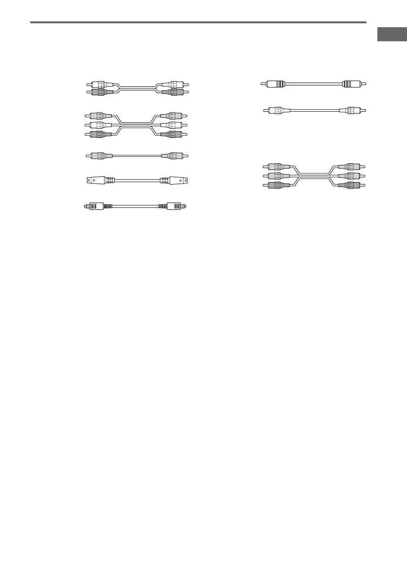
Required cords
The hookup diagrams on the subsequent pages assume the use of the following optional connection
cords (A to H) (not supplied).
A Audio cord
White (L)
Red (R)
B Audio/video cord
Yellow (video)
White (L/audio)
Red (R/audio)
C Video cord
Yellow
D S-video cord
E Optical digital cord
F Coaxial digital cord
G Monaural audio cord
Black
Tip
Audio cord A can be torn into two monaural audio
cords G.
H Component video cord
Green
Blue
Red
Notes
• Turn off the power to all components before making any connections.
• Be sure to make connections firmly to avoid hum and noise.
• When connecting an audio/video cord, be sure to match the color-coded pins to the appropriate jacks on the
components: yellow (video) to yellow; white (left, audio) to white; and red (right, audio) to red.
• When connecting optical digital cords, insert the cord plugs straight in until they click into place.
• Do not bend or tie optical digital cords.
GB01COV_STR-DB798-CEL.book Page 5 Thursday, August 18, 2005 8:59 AM

 Loading...


