Do you have a question about the Sony STR-W555 and is the answer not in the manual?
Detailed power output, RMS power, and music power ratings for the amplifier.
Tuning ranges, aerial types, and intermediate frequencies for FM, UKV, and AM tuners.
Input specifications for video signals, including voltage and impedance.
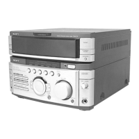
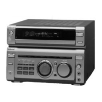
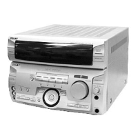
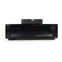
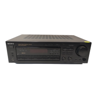
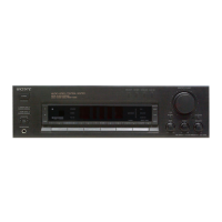
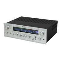
Identifies and describes all controls and indicators on the front panel of the unit.
Step-by-step instructions for disassembling the sliding panel mechanism.
Diagrams and notes on connecting the unit for servicing or standalone operation.
Instructions for performing cold and hot resets to restore initial conditions or memory.
Details on CD Delivery Mode, Sled Servo Mode, and function name changes.
Procedure for adjusting the AM tuner's signal level for optimal performance.
Procedure for adjusting the FM tuner's signal level for optimal performance.
Specific FM tuning adjustments for certain regional models.
Diagram showing the physical placement of all circuit boards within the unit.
High-level functional diagrams illustrating signal paths and major circuit blocks.
Detailed electronic circuit schematics for various sections of the unit.
Layout diagrams showing component placement and routing on printed circuit boards.
Functional diagrams and pin assignments for integrated circuits used in the unit.
Exploded view of the outer casing and the sliding panel mechanism.
Exploded view of the front panel components and assembly.
Detailed exploded view of the unit's slide mechanism components.
Exploded views showing circuit boards and the back panel assembly.
List of electronic components for detector, AV, headphone, and loading panel boards.
Parts list for power amplifier, primary, secondary, and surround speaker sections.
Comprehensive parts list for the TCB board, including components, filters, and connectors.
| Power Output | 100W per channel (8 ohms, 20Hz-20kHz, 0.09% THD) |
|---|---|
| Frequency Response | 10Hz-100kHz (+0.5dB, -3dB) |
| Total Harmonic Distortion | 0.09% |
| Input Sensitivity (phono) | 2.5mV |
| Signal-to-Noise Ratio | 85dB (phono), 100dB (line) |
| Dimensions | 430 x 157 x 370 mm |
| Weight | 11.5 kg |
| Input sensitivity (MM) | 2.5mV |
| Input sensitivity (line) | 150mV |
| Impedance | 8 ohms |
| Speaker load impedance | 8 ohms |