Functional Overview
WFM 1125 Option 0A/0B/0C/0D User Manual
2-3
Table 2-1: Front panel functions (cont.)
Front panel items DescriptionsItem name
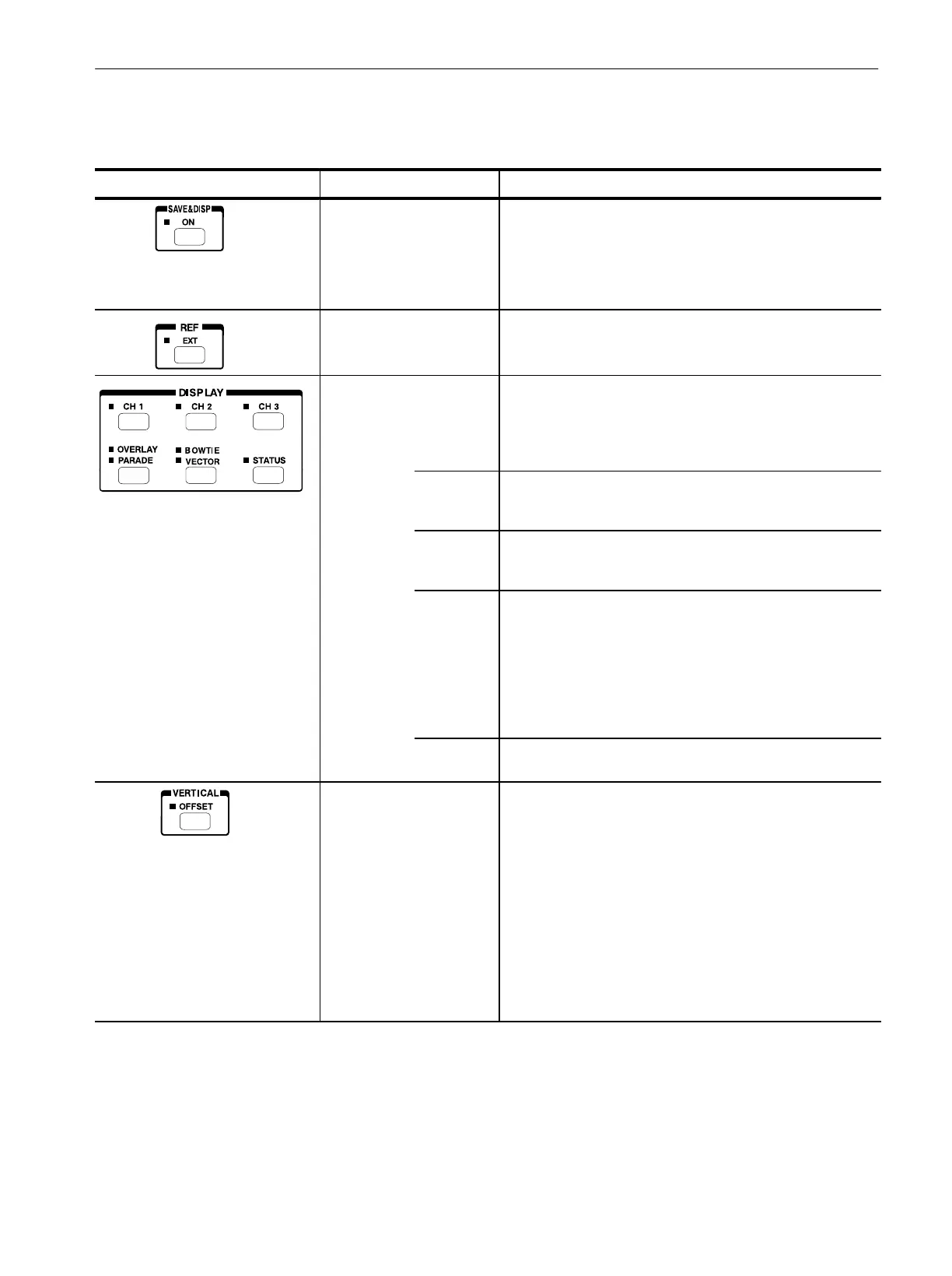
SAVE&DISP ON button Stores the displayed waveform in the internal memory and
reĆdisplays the stored waveform on the screen. When the
waveform stored in the memory is displayed, the LED lights. For
the purpose of comparison, the incoming video signal is also
displayed. When you switch to another display mode or press this
button again, this mode will be cancelled.
REF EXT button Selects either internal serial digital or external composite video
input for the instrument synchronization reference.
DISPLAY Controls the type of display. The six buttons in the DISPLAY area
generally represent two related types of displays. Press a button
to select one of its two displays. Press the button again to select
the other. When you select a display type, the indicator beside it
lights up.
CH1, CH2,
and CH3
buttons
Allow you to select the corresponding channel. When you select
a channel with the button, the video signal coming from that
channel is displayed in the volts vs. time graticule on the screen.
OVERLAY /
PARADE
button
Displays three channels of the video signal at the same time or
displays up to three channels of the video signal in succession.
BOWTIE /
VECTOR
button
Displays a bowtie test signal or displays the component signals in
Vector displays. You can toggle between the Bowtie and Vector
display. For the Vector display, you can select from among three
display modes: VECTOR, LIGHTNING, and DIAMOND. For
Option 0A, 240M/274M format mode of Option 0C, or Interlace
and Segment Frame modes of Option 0D, in VECTOR or
LIGHTNING mode, you can choose either of two scales: one for
BTA format or one for ITUĆR format.
STATUS
button
Displays digital component video signal in hex or decimal.
VERTICAL OFFSET button
Selects a waveform to which the V POS knob operates. This
mode will be disabled if you select the Vector display or Status
display. Only the RESET is available if you perform a single
channel display. You have several options from the menu:
CH1 : Selects channel 1.
CH2 : Selects channel 2.
CH3 : Selects channel 3.
ALL : Selects all channels.
RESET : Resets the offset of the currently selected channel to
the default value.
 Loading...