5-1
SECTION 5
CIRCUIT ADJUSTMENTS
5-1. BK Board
5-1-1. Adjustments 1
Set as follows at the INPUT CONFIGURATION menu of the SETUP menu.
FORMAT ............... COMPONENT YUV SMPTE/EBU N-10
SLOT NO............... 6
SYNC MODE ........ INT
Select BK BOARD DATA LOAD from BK BOARD menu of MAINTENANCE menu and execute.
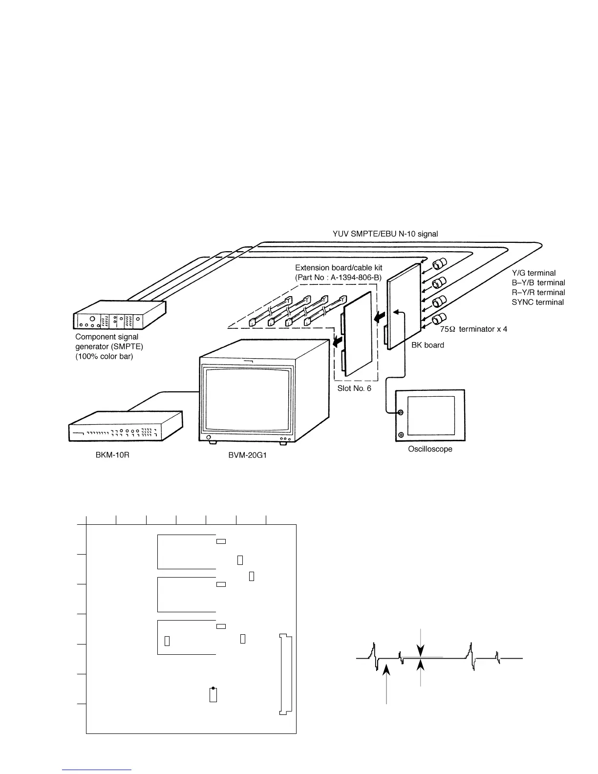
• Connection
• Arrangement Diagram for Adjustment Parts
1234567
A
B
C
D
E
F
G
TP104
TP101
TP102
TP304
TP506
TP504
TP502
IC701
1
8
16
9
CN1
BK board –A SIDE–
Fig. 5-2
Fig. 5-1
1. Bright Center Adjustment
1. Input the component color bar signal (YUV SMPTE/
EBU N-10).
2. Set the BRIGHT data to 2048 using the BRIGHT knob.
3. Connect an oscilloscope to pin !∞ of IC701 of the BK
board.
4. As shown in Fig. 5-3, adjust the BRT CENTER data so
that the waveform becomes flat.
Note: The BRT CENTER adjustment menu is under the
BK BOARD menu of the MAINTENANCE
menu.
Position of W/B insert pulse
Make flat
Level difference: 0 ±8 mV
Fig. 5-3