5-10
5-2. BC Board
5-2-1. Adjust Preparation
Set 1CH as follows using INPUT CONFIGURATION menu of the SETUP menu.
FORMAT .................... COMPONENT YUV SMPTE/EBU N-10
SLOT NO .................... 6
SYNC MODE ............. INT
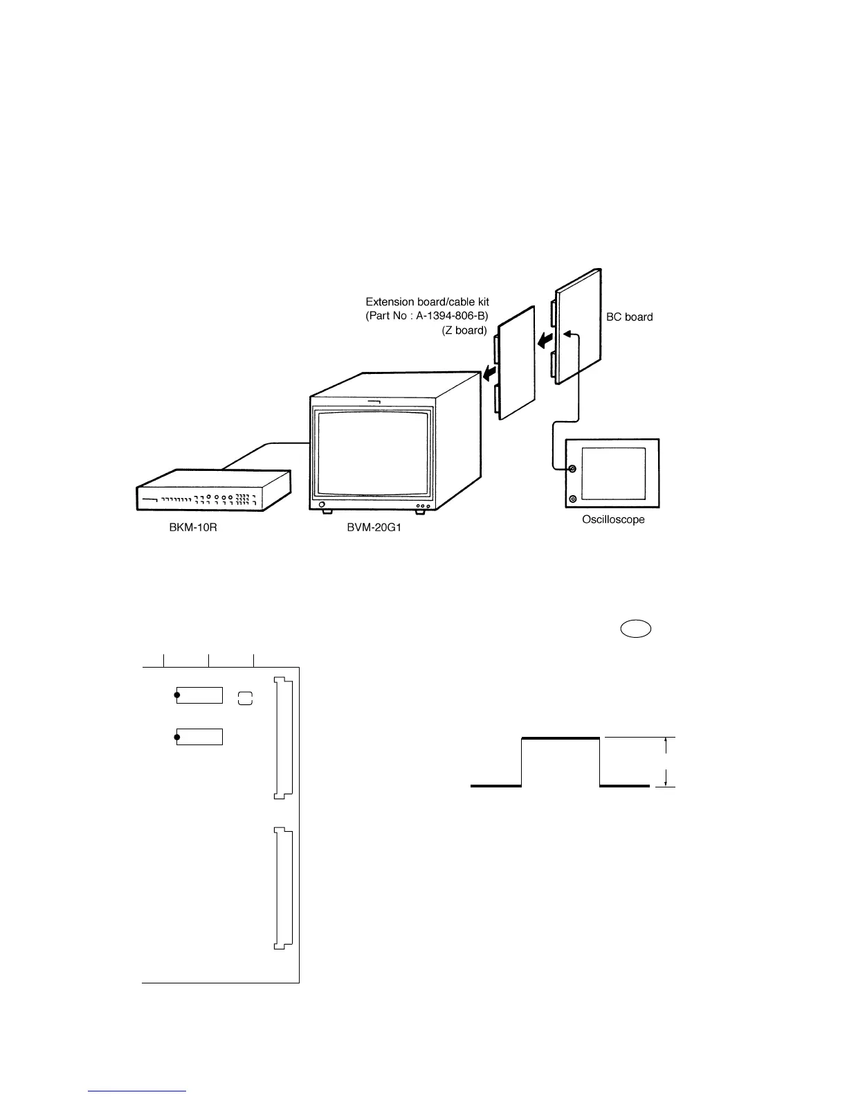
• Connection
Fig. 5-19
• Arrangement Diagram for Adjustment Parts 5-2-2. D/A Level Adjustment
1. Connect the oscilloscope to pin B10 of CN1 of the BC
board.
2. Select the 93-ch menu on the MAINTENANCE menu
and output an internal white signal.
3. Adjust RV101 so that the 660 ±20 mV.
567
IC108
CN1
CN2
BC board –A SIDE–
28 15
114
IC107
28 15
114
RV101
1
32
1
32
Fig. 5-20
660 ±20 mV
Fig. 5-21
5-2-3. SETUP Level of Built-in Signal and
100 IRE Level is Automatic operation.
1. Select the EXTEND menu of SETUP menu.
2. Select the ADJ INT SIGNAL menu and SETUP level of
built-in signal and 100 IRE level is automatic operation
and execule.
3. Displayed the PROCEDER COMPLETED is after 10 to
15 second and automatic operation is completion.