CPD-E500/E500E
CN801
9
10
8
7
6
Open the D block.
(Refer to 2-2.)
GND
CN5
CN4
A board
Open the G block.
(Refer to 2-3.)
Neck assembly
Deflection yoke
Picture tube
Three connectors
Anode cap
(See page 2-6.)
1
2
3
4
5
Four screws
(Tapping screw 5)
Bezel assembly
4
6
8
7
Four screws
(Tapping screw 5)
H1 board
Two screws
(+ BVTP 4 x 16)
Bezel assembl
2
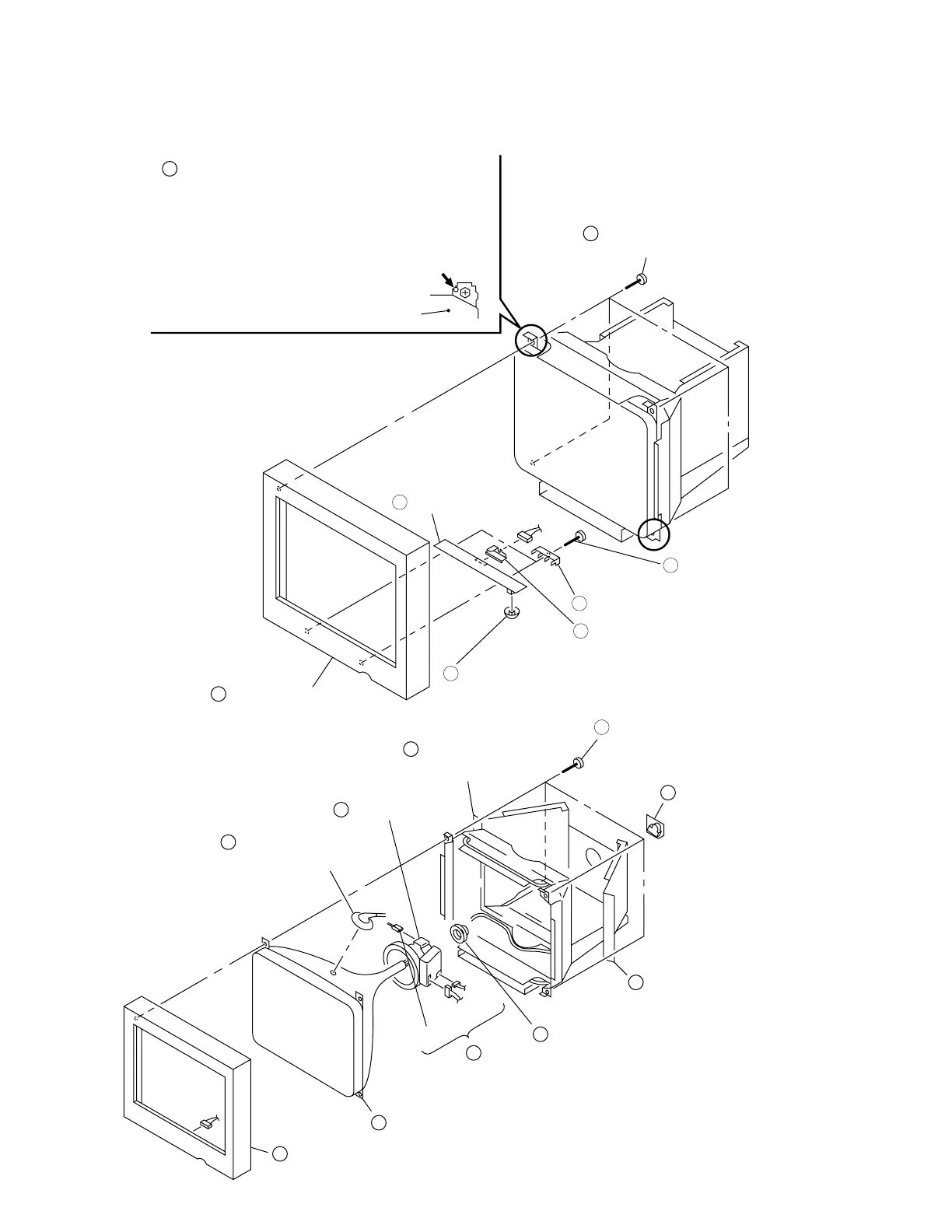
Before removing the bezel assembly, secure
the picture tube by attaching two screws to
the picture tube shield at the positions
shown with an arrow (diagonal two places)
to prevent the picture tube from falling. (Use
the screws +BVTT 4 x 8 that fix top cover.)
1
3
CN801
Picture tube shield
Two H printed circuit board brackets
Menu button
5
H printed
circuit board
cover
2-7. BEZEL ASSEMBLY, H1 BOARD REMOVAL
2-8. PICTURE TUBE REMOVAL
2-5