CPD-E500/E500E
c
Anode Button
b
a
CN891
CN601
GND
3
4
5
2
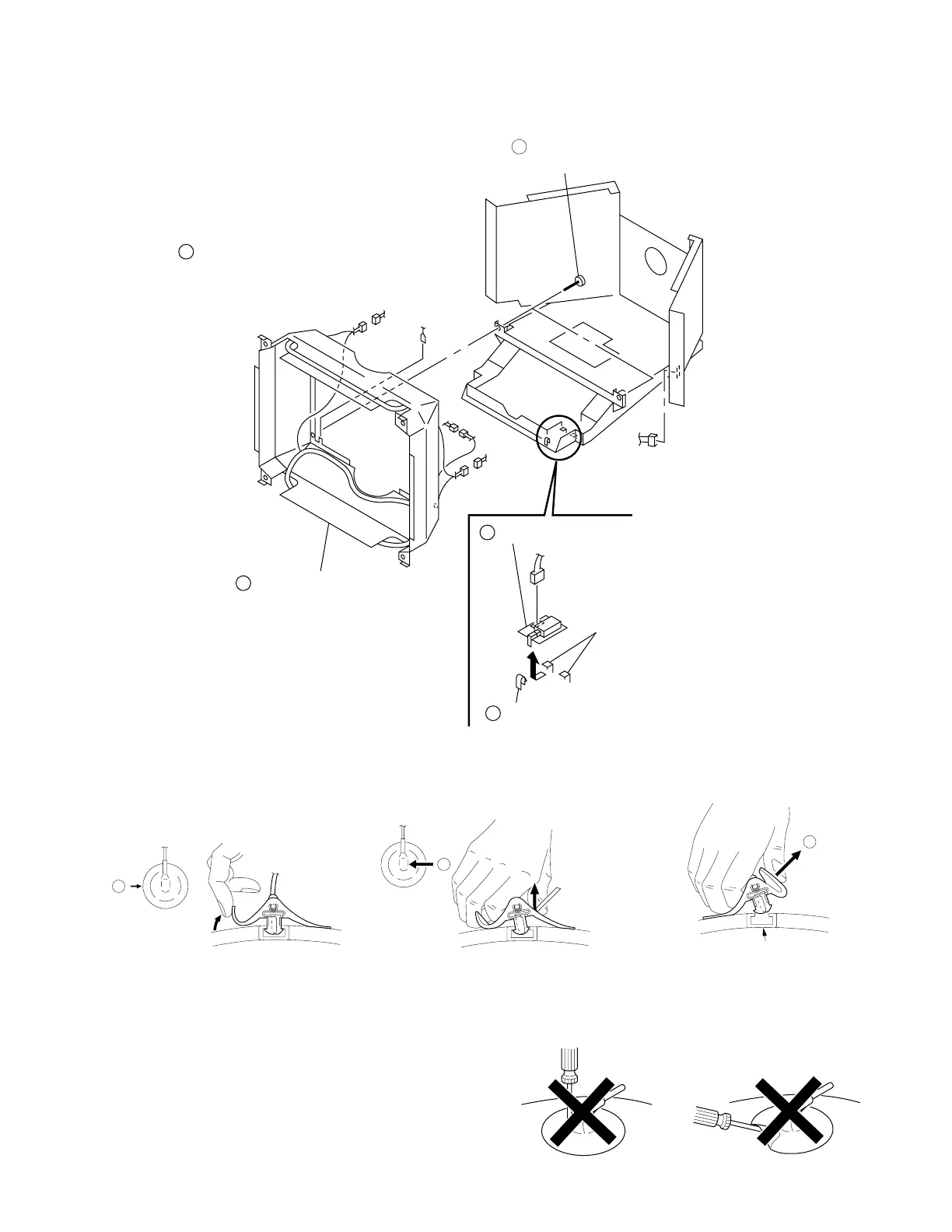
J board
Claw
Two hooks
Remove the picture tube.
(Refer to 2-8.)
1
Two screws
(+BVTT 4 x 8)
4pin
4pin
2pin
Picture tube shield
complete assembly.
2-9. J BOARD REMOVAL
2-6
3 When one side of the rubber cap is
separated from the anode button, the
anode-cap can be removed by turning
up the rubber cap and pulling up it in the
direction of the arrow c.
• HOW TO HANDLE AN ANODE-CAP
1 Don’t scratch the surface of anode-caps with sharp shaped
material!
2 Don’t press the rubber hardly not to damage inside of anode-
caps!
A material fitting called as shatter-hook terminal is built in the
rubber.
3 Don’t turn the foot of rubber over hardly!
The shatter-hook terminal will stick out or damage the rubber.
• REMOVAL OF ANODE-CAP
NOTE: Short circuit the anode of the picture tube and the anode cap to the metal chassis, CRT shield or carbon painted on the CRT, after
removing the anode.
• REMOVING PROCEDURES
1 Turn up one side of the rubber cap in
the direction indicated by the arrow a.
2 Using a thumb pull up the rubber cap
firmly in the direction indicated by the
arrow b.