OV
GIR
Level
lJ
L
-45
±2
V
Fig.
2-1-3
2)
Coarse
adjustment
(1)
Set
the
CONT
VR
to
minimum.
(2)
Adjust
the
SCREEN (G2) VR so
that
the
back-
ground
of
the
screen disappears.
(3)
Adjust
the
RV404
(G-BKG) and RV405 (B-BKG)
for dark level white balance.
(4)
Set
the
CONT
VR
to
maximum.
(5) Adjust
the
RV402
(G-DRV) and RV403 (B-DRV)
for
the
high-light white balance.
(6)
Repeat from
(1)
to
(5) until getting
the
good
white balance. (This adjustment need
not
be
precise.)
2-2.
Beam
Landing Coarse Adjustment
If
you use the CRT of FRU provided by SONY, you
need
not
do adjustments decribed below.
1)
Input
a full white signal
(or
equivalent signal).
2)
Rotate
the
CONT
VR
fully clockwise.
3) Project only green (switch
off
SG
Rand
B channel
outputs).
4)
Adjust SCREEN
(G2)
VR
to
obtain
appropriate
brightness.
5)
Move
the
DY backward and make a coarse adjust-
ment
with
the
purity
magnet so
that
the
green raster
is
at
the
screen center. (see Fig. 2-2-1)
6)
Move
the
DY forward and adjust so
that
the
entire
screen turns green.
7) Adjust the
DY
tilt.
8) Lightly fix
the
DY
with
the
DY
fixing bracket.
R
G
B
Fig. 2-2-1
4-2
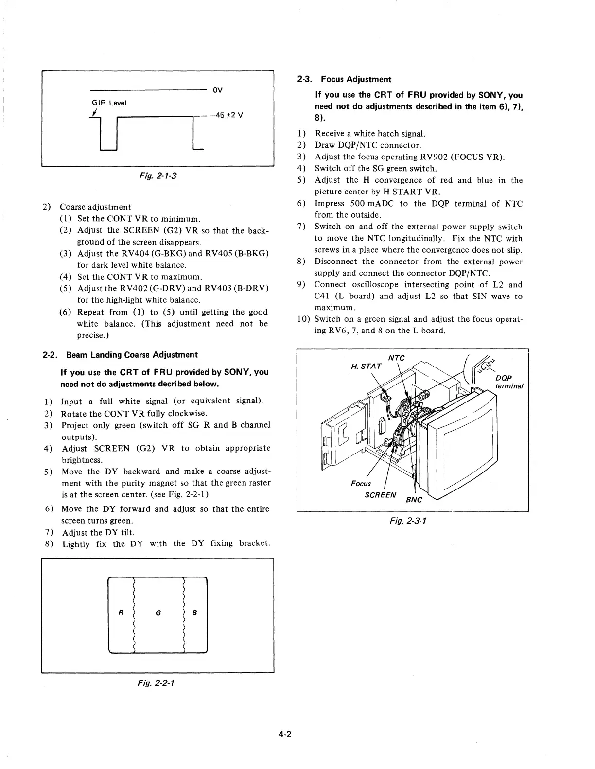
2-3. Focus Adjustment
If
you use the CRT of FRU provided by SONY, you
need not do adjustments described
in
the item
6),7),
8).
I)
Receive a white
hatch
signal.
2)
Draw DQP/NTC connector.
3)
Adjust
the
focus operating
RV902
(FOCUS VR).
4)
Switch
off
the
SG green switch.
5) Adjust
the
H convergence
of
red and blue
in
the
picture center by H START YR.
6)
Impress
500
mADC
to
the
DQP terminal
of
NTC
from
the
outside.
7)
Switch
on
and
off
the
external power supply switch
to
move
the
NTC longitudinally.
Fix
the NTC
with
screws
in
a place where
the
convergence does not slip.
8)
Disconnect
the
connector
from
the
external power
supply and connect
the
connector
DQP/NTC.
9)
Connect oscilloscope intersecting point
of
L2 and
C41 (L board) and adjust L2 so
that
SIN wave
to
maximum.
10) Switch
on
a green signal and adjust
the
focus operat-
ing RV6, 7, and 8
on
the
L board.
Fig. 2-3-1
 Loading...