2-4. Convergence Coarse Adjustment
If
you
use
the
CRT
of
FRU provided by SONY,
you
need
not
do
adjustments described
in
the
item
2),5),
6).
I)
Receive a white
hatch
signal.
2) Operate
the
BMC
magnet and adjust
the
BMC
in
horizontal and vertical directions
of
the
picture.
3)
Operate
the
H STAT
VR
and adjust
the
convergence
in
the
picture center.
4)
Operate V CONY
(RVI,
2, and
3)
on
the
L board and
adjust
the
V convergence.
RV1-
RV2-
RV3_
Fig. 2-4-1
Cscrew
Bscrew
Fig. 2-4-2
5)
Adjust XBV
and
XCV by
the
reactor
on
the
right side
seen from
the
CRT.
6)
Adjust H AMP and H
TILT
by
the
reactor
on
the
left
side seen from
the
CRT.
4-3
XBV
HAMP
[23
R B
R
B
I
i
I
I
....
",
......
I
I
B
I
I
XCV
H
TILT
X
R
B
B R
I
,
I
I
I
I
.....
I
I
I
I
Fig. 2-4-3
2-5. Beam Landing Adjustment
If you use
the
CRT
of
FRU provided by SONY, you
need
not
do
adjustments described below.
I)
Put
the
monitor
in
the
Helmholtz room.
(BII
= 0,
Bv
=
-0.35
gauss)
2)
Input
a full white signal
(or
equivalent signal), and
tum
the
Blue and Red channel off.
3)
Set
the
CONT
VR
to
maximum.
4) Degauss
the
screen by
the
hand degauss coil.
5) After more
than
30
minutes aging,
attach
the
landing
checker and adjust the DY position,
the
purity
control,
the
DY tilt and the landing
of
4 comers.
The landing deviation have
to
be
less
than
± I
OJ.(m
of
4 corners.
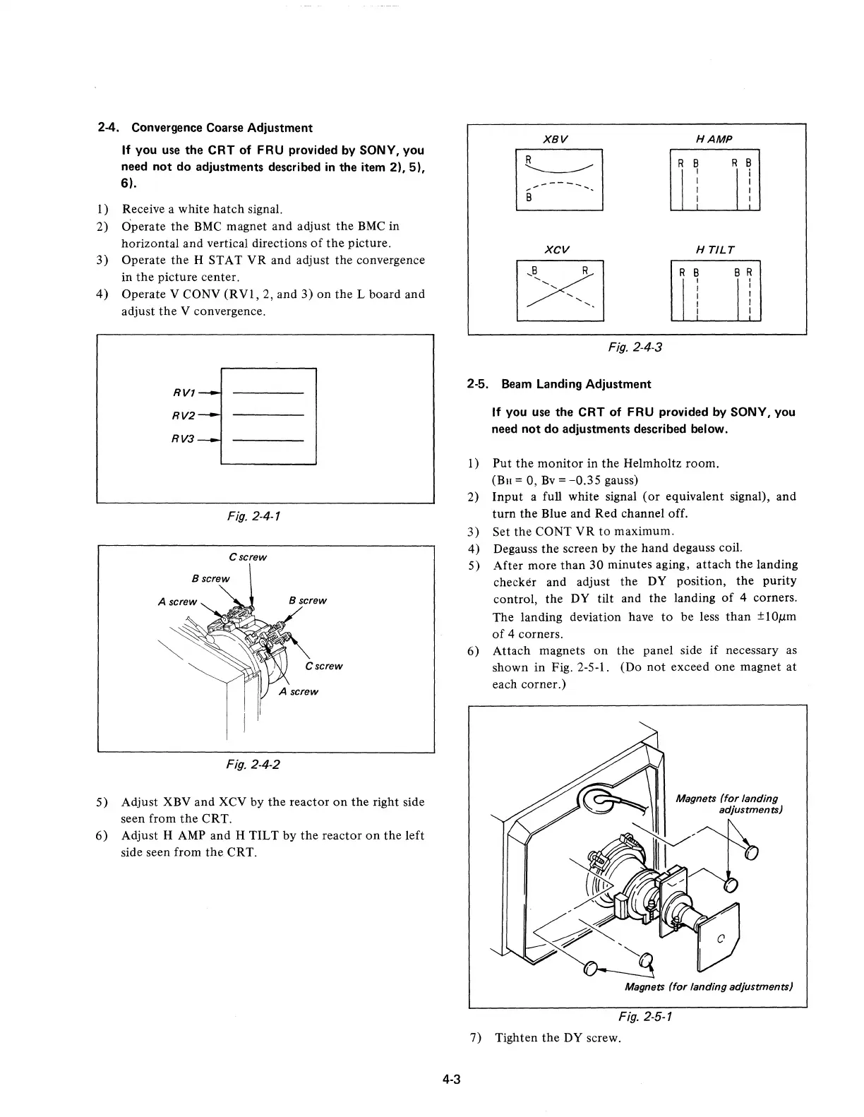
6)
Attach
magnets
on
the
panel side
if
necessary as
shown
in
Fig. 2-5-1. (Do
not
exceed one magnet
at
each corner.)
Magnets
(for
landing adjustments)
Fig. 2-5-1
7) Tighten
the
DY screw.
 Loading...