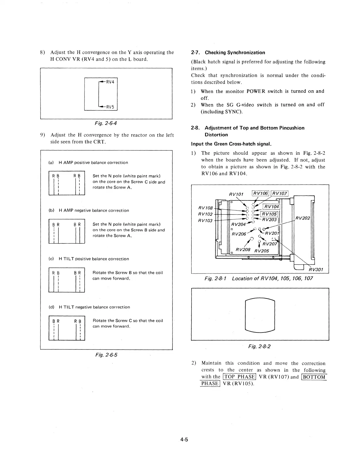
8)
Adjust
the
H convergence
on
the
Y axis operating
the
H CONY
VR
(RV4 and 5)
on
the
L board.
I[1
RV4
LW
Fig.
2·6·4
9) Adjust
the
H convergence by
the
reactor
on
the
left
side seen from
the
CRT.
(a) H AMP positive balance
correction
R
~
I
I
I
I
Set
the
N pole (white paint mark)
on
the
core
on
the
Screw C side
and
rotate
the
Screw A.
(b) H AMP negative balance
correction
Set
the
N pole (white paint mark)
on
the
core
on
the
Screw B side
and
rotate
the
Screw A.
(c) H TI L T positive balance
correction
R B
Ii
B R
,
I
I
I
I
Rotate
the
Screw B so
that
the
coil
can move
forward.
(d) H TI L T negative balance
correction
Rotate
the
Screw C so
that
the
coil
can move
forward.
Fig.
2·6·5
4·5
2-7. Checking Synchronization
(Black
hatch
signal
is
preferred for adjusting the following
items.)
Check
that
synchronization is
normal
under
the
condi-
tions described below.
l)
When
the
monitor
POWER switch
is
turned
on
and
off.
2) When
the
SG G-video switch
is
turned
on
and
off
(including SYNC).
2-8. Adjustment
of
Top and Bottom Pincushion
Distortion
Input the Green Cross-hatch signal.
1)
The
picture should appear
as
shown
in Fig. 2·8-2
when
the
boards have been adjusted.
If
not,
adjust
to
obtain
a
picture
as
shown
in Fig. 2·8-2 with
the
RVI06
and
RVI04.
RV101
o •
,;--;
I RV1041
RV108
m'l"itt--_-<"-;
::--=
RV102
.;
::~IRV10511
RV103
';
':"';--RV2031
RV204"-"
~V206/)
~RV20J
.,
,
.-
/.
l'RV207
o
RY208
R
V205
RV202
RV301
Fig.
2-8·1 Location
of
RV104, 105, 106, 107
Fig.
2·8·2
2) Maintain this
condition
and
move
the
correction
crests
to
the
center
as
shown
in
the
following
with
the
ITOP PHASEI
VR
(RVI07)
and IBOTTOM
PHASE I
VR
(RVI05).
 Loading...