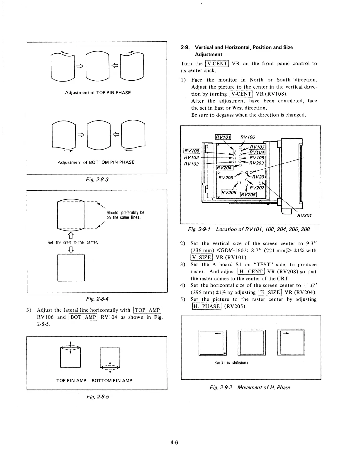
Adjustment
of
TOP PIN PHASE
Adjustment
of
BOTTOM PIN PHASE
Fig. 2-8-3
0
------
-,
Should
preferably
be
on
Ihe
some
lines.
------
-_/
D'
Sel
Ihe
cresl
10
Ihe
cenler.
.(J,
D
Fig. 2·8-4
3)
Adjust
the
lateral line horizontally with I TOP
AMP
I
RVI06
and I BOT
AMPI
RVI04
as
shown in Fig.
2-8-5.
TOP PIN AMP BOTTOM PIN AMP
Fig. 2-8-5
4·6
2-9. Vertical and Horizontal, Position and Size
Adjustment
Turn
the
I V -CENT I V R
on
the
front panel
control
to
its
center
click.
I)
Face
the
monitor in North
or
South
direction.
Adjust
the
picture
to
the
center in
the
vertical direc-
tion
by turning I V -CENT I
VR
(RV 1 08).
After the adjustment have been completed, face
the
set in East
or
West direction.
Be
sure
to
degauss when
the
direction
is
changed.
IRv1011
RV106
~
':v,RV101
i!JJ!J!l!lJT1I"'I-1tt-_..;.-\~
;;-,--1
R
V1
041
RV102
.:'
':l-4-RV105
RV103
",
('--RV203
IRv2041-"
°RV206/)
~RV20j
/~
~VI~}
o~
RV205
RV301
Fig. 2·9·7 Location
of
RV107,
708,204,205,208
2)
Set
the
vertical size
of
the
screen center
to
9.3"
(236
mm)
<GDM-1602:
8.7"
(221 mm»
±1%
with
Iv
SIZEI
VR
(RVI0l).
3)
Set
the
A board S 1 on
"TEST"
side,
to
produce
raster. And adjust I
H.
CENT I
VR
(RV208)
so
that
the
raster comes
to
the
center
of
the
CRT.
4)
Set
the
horizontal size
of
the screen center
to
11.6"
(295
mm)
±l%
by adjusting IH. SIZEI
VR
(RV204).
5)
Set the picture
to
the
raster center by adjusting
IH. PHASEI (RV205).
ODD
Rasler
is
stationary
Fig. 2·9·2 Movement
of
H.
Phase
 Loading...