– 65 –
KV-DA29M81
RM-W105
7-2. SCHEMATIC DIAGRAM INFORMATION
Note:
• All capacitors are in µF unless otherwise noted.
• All electrolytic capacitors are rated at 50V unless otherwise noted.
• All resistors are in ohms.
kΩ = 1000Ω, MΩ = 1000kΩ
• Indication of resistance which does not have rating electrical
power is as follows.
Pitch: 5 mm
Rating electrical power 1/4W (CHIP: 1/10W)
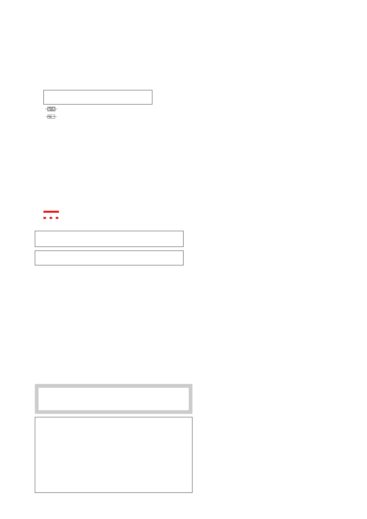
• : nonflammable resistor.
• : fusible resistor.
• ¢ : internal component.
• : panel designation or adjustment for repair.
• All variable and adjustable resistors have characteristic curve B
unless otherwise noted.
• Readings are taken with a color-bar signal input.
no mark : Common
(): PAL
[ ] : NTSC 3.58
• Readings are taken with a 10MΩ digital multimeter.
• Voltage are dc with respect to ground unless otherwise noted.
• Voltage variations may be noted due to normal production
tolerances.
• All voltage are in Volt.
• ✽ : Cannot be measured.
• Circled numbers are waveform references.
• : B +bus.
• : B –bus.
• k : signal path.
Note: The reference number which starts with Wxxx
(eg: W003) indicates a wire to wire connection.
Note: Components marked as XX are not fitted on
this model.
Reference information
RESISTOR : RN METAL FILM
: RC SOLID
: FPRD NONFLAMMABLE CARBON
: FUSE NONFLAMMABLE FUSIBLE
: RS NONFLAMMABLE METAL OXIDE
: RB NONFLAMMABLE CEMENT
: RW NONFLAMMABLE WIREWOUND
: ✽ ADJUSTMENT RESISTOR
COIL : LF-8L MICRO INDUCTOR
CAPACITOR : TA TANTALUM
: PS STYROL
: PP POLYPROPYLENE
: PT MYLAR
: MPS METALIZED POLYESTER
: MPP METALIZED POLYPROPYLENE
: ALB BIPOLAR
: ALT HIGH TEMPERATURE
: ALR HIGH RIPPLE
Note: The component identified by shading and mark
! are critical for safety. Replace only with part
number specified.
Note: "A" board schematic diagram is divided into 4 blocks.
"BH1" board schematic diagram is divided into 2 blocks.
"D" board schematic diagram is divided into 2 blocks.
"VM" board schematic diagram is divided into 2 blocks.
Each block is named by its function and block "number".
eg: Hercules/Tuner/Audio/Regulator (Block 001) Joint
connection between boards can be identified using the
block number followed by the grid's guide.
eg: –< NVM_SCL
003:1I
Meaning: Block 001 joint "NVM_SCL" is connected to
Block 003 joint "NVM_SCL" located at grid 1I.



 To Next Page