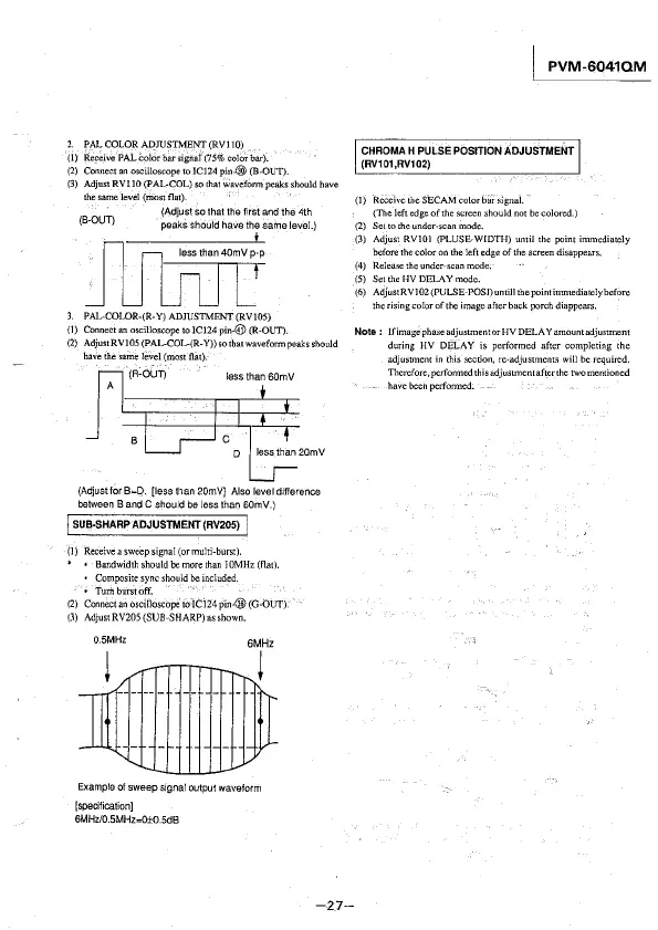
2. PAL COLOR ADJUSTMENT (RVI 10)
(I) Receive PAL
Color bar signal (75% color bar).
(2) Connect an oscilloscope to IC124 pin-@ (B-OUT).
(3) Adjust RVIIO (PAL-COL} so that wavefonn peaks should have
thesamelevel(mostflat).
(Adjust so that the first and 1he 4th
(B-OUT) peaks should have the same level.)
3. PAL-COLOR-(R-Y) ADJUSTMENT (RV105)
{I)
Connect an oscilloscope to ICI24 pin-@ (R-OUT).
(2) AdjustRVI05(PAL-COL-(R-Y))sothatwaveformpeaksshould
have the same level (most flat).
(R-OUT)
less than 60mV
A
(Adjust for
B=D. [less than 20mVJ Also level difference
between 8 and C should be less than B0mV.)
I SUB-SHARP ADJUSTMENT (RV205) I
(1) Receive a sweep signal (ormu!ti-burst).
* • Bandwidthshouldbemorethan J0MHz(fla!).
• Composite sync should be included.
•
Turilburstoff.
(2) Connect an oscilloscope to !Cl 24 pin-@ (G-bUT).
(3) Adjust RV205 (SUB"SHARP) as shown.
0.5MHz
6MHz
i
Example of sweep signal output waveform
[specification]
6MHz/0.SMHz=0±0.5dB
-27-
I PVM-6041QM
CHROMA H PULSE POSITION ADJUSTMENT
(RV101,RV102)
(]) Receive the SEC AM color bai-signal.
(The left edge of
the screen should not be colored.)
(2) Set to the under-scan mode.
(3) Adjust RYIOJ (PLUSE.WIDTH) until the point immediately
before the color on the left
edge of the screen disappears.
(4) Release the under-scan mode.
(5) Set the HY DELAY mode.
(6) AdjustRY102(PULSE-POSJ) um ill the point immediately before
the rising color of the image after back porch diappears.
Note: IfimagephaseadjustmentorHY DELA Yamountadjustment
during HY DELAY is performed after completing the
adjustment in this section,
re-adjustment~ will be required.
Therefore,perfonne.dthisadjustmentafterthe twomentioned
havebeenpetfonned.