23
KV-21FK120
KV-21FK120
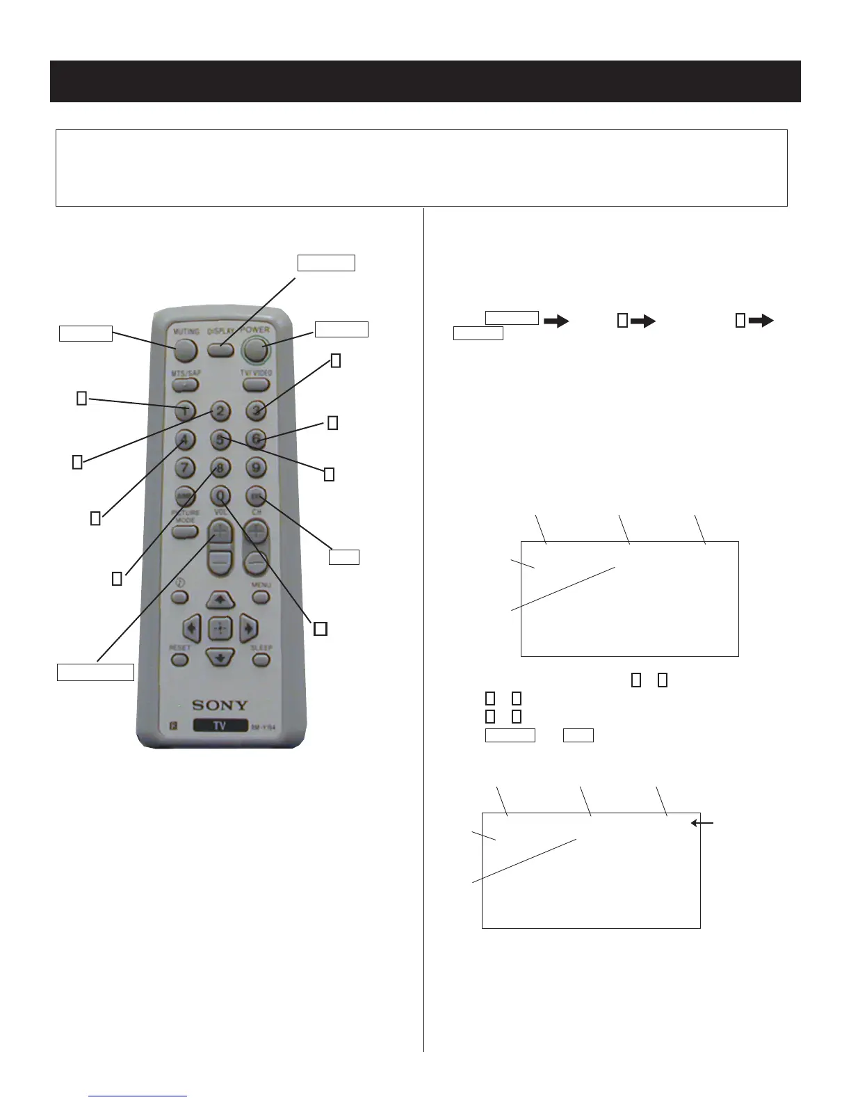
Electrical Adjustments by Remote Commander
Use the Remote Commander
(RM-Y194) to perform the circuit adjustments in this section.
Test Equipment Required: 1. Pattern generator 2. Frequency counter 3. Digital multimeter 4. Audio oscillator
SECTION 4: CIRCUIT ADJUSTMENTS
4-2. ACCESSING SERVICE ADJUSTMENT
MODE
Service Mode Procedure
1. Standby mode (power off).
2. Press
DISPLAY
Channel
5
Sound Volume
+
POWER
on the Remote Commander (press each button within a
second).
NOTE: Setting the set in VIDEO mode will make it easier to read the
service data.
Service Adjustment Mode On
The CRT displays the fi rst Category in the Service list.
Category
Display
Item
Display
Data
Signal
Type
Channel
Type
NTSC VIDEO1DEF
M655E2AMF-107FP
S 3.OD
HSIZ 1 : 51 NVM:OK
1. On the Remote Commander, press
2
or
5
to select the Category.
2. Press
1
or
4
to select the Item.
3. Press
3
or
6
to change the Data.
4. Press
MUTING
then
ENT
to write into the memory.
Category
Display
Item
Display
Data
Signal
Type
Channel
Type
Text changes
to “WRITE”
and changes
from green to red
NTSC WRITEDEF
M655E2AMF-107FP
S 3.OD
HSIZ 1 : 51
4-1. REMOTE ADJUSTMENT BUTTONS AND
INDICATORS
VOLUME (+)
(Service Mode)
ENT
(Enter into
memory)
0
(Remove
from
memory)
3
(Adjust)
Data up
RM-Y194
5
(Display)
Category
down
MUTING
(Enter into
memory)
1
(Display)
Item up
2
(Display)
Category up
4
(Display)
Item down
8
(Initialize)
DISPLAY
(Service Mode)
POWER
(Service Mode)
6
(Adjust)
Data down