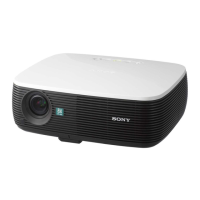
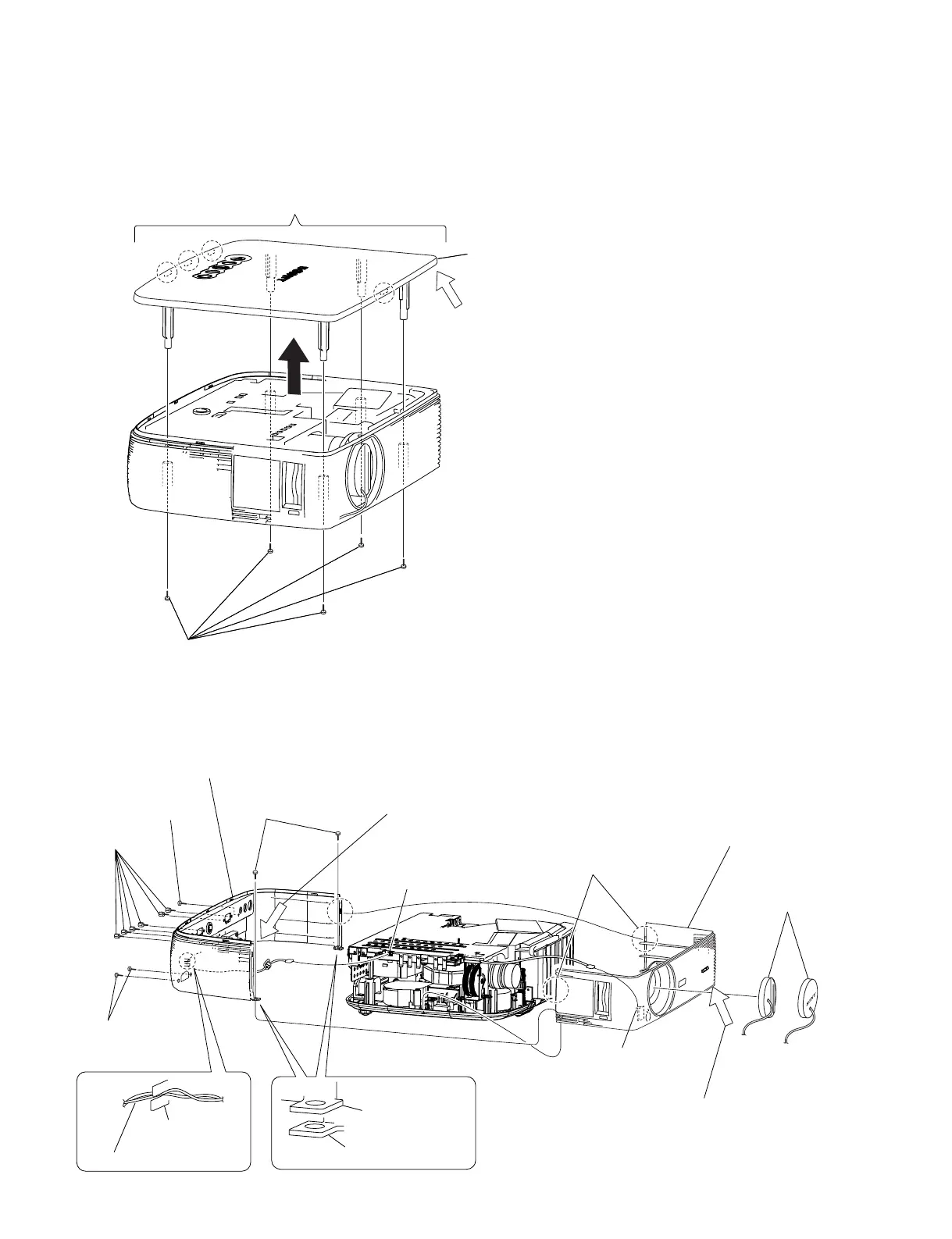
1-2
VPL-ES4/EX4
1-3. Disassembly
1-3-1. Upper Case Assembly
1-3-2. Front Case Assembly and Sub Rear Case Assembly
Remove the upper case assembly before starting the removal work.
VPL-ES4 VPL-EX4
4
Two screws
(M 3 x 6)
5 S
crew
(M 3)
!=
Sub rear case assembly
7
Two screws
(+K 3 x 12)
6
Six
hexagon
screws
![
Front case assembly
1
Lens cap
0
Two claws
2
Main board
connector (J6)
3
IR sensor board
connector (J1)
Sub rear case
assembly
Sub rear case
assembly
!-
Speaker harnesses
9
Remove the upper case assembly from this corner with the
strong force to the extent that the upper case assembly will
not be damaged.
8
Remove the upper case assembly from this corner with the
strong force to the extent that the upper case assembly will
not be damaged.
Front case assembly
2
Four claws
4 Upper case assembly
3
Remove the upper case assembly from this corner with the
strong force to the extent that the upper case assembly will
not be damaged.
1
Five screws (M 3 x 6)