13
WM-FX522
• AM alignment should be done with mechadeck attached.
•Repeat the procedures in each adjustment several times for a
maximum reading on level meter.
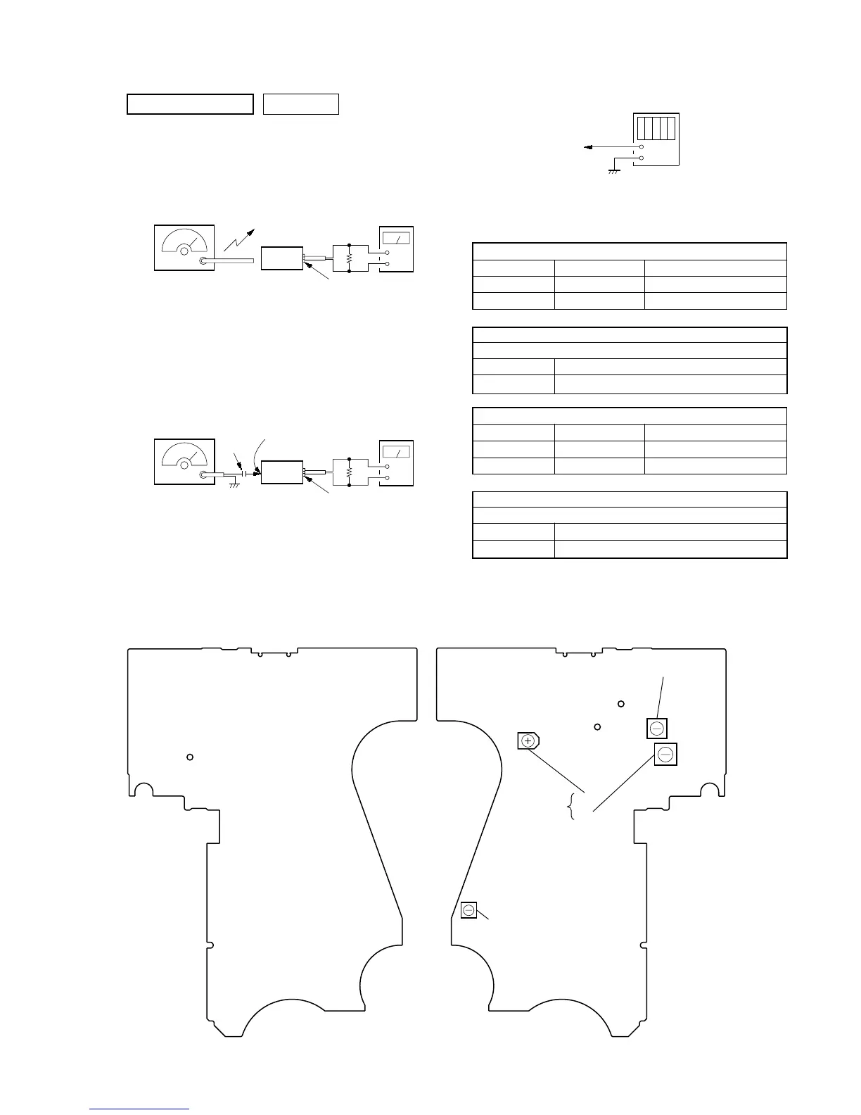
AM VT VOLTAGE ADJUSTMENT
Adjustment Part Frequency Display Reading on Digital Voltmeter
Confirmation 531kHz 1.3 ± 0.3 V
Confirmation 1602 kHz 7.0 ± 0.5 V
AM TRACKING ADJUSTMENT
Adjust for a maximum reading on level meter
L5 621 kHz
CT1 1395 kHz
FM VT VOLTAGE ADJUSTMENT
Adjustment Part Frequency Display Reading on Digital Voltmeter
Confirmation 87.5 MHz 3.85 ± 0.5 V
Confirmation 108 MHz 7.7 ± 1 V
FM TRACKING ADJUSTMENT
Adjust for a maximum reading on level meter
L7 87.5 MHz
Confirmation 108 MHz
TUNER SECTION 0 dB=1 µV
[AM]
Setting:
function : RADIO
BAND button : AM
[FM]
Setting:
function : RADIO
BAND button : FM
 Loading...