EasyManua.ls Logo

Sony WM-FX522 User Manual

Sony WM-FX522
32 pages
To Next Page IconTo Next Page
Page #1 background imageLoading...
Page #1 background image
SERVICE MANUAL
Ver 1.0 2003.01
9-874-226-01 Sony Corporation
2003A0500-1 Personal Audio Company
C 2003.01 Published by Sony Engineering Corporation
RADIO CASSETTE PLAYER
AEP Model
SPECIFICATIONS
WM-FX522
Model Name Using Similar Mechanism WM-FX521
Tape Transport Mechanism Type MT-WMEX505-162
Radio section
Frequency range
FM: 87.5 - 108 MHz
AM: 531 - 1 602 kHz
Tape section
Frequency response
Playback: 40 - 15 000 Hz
Output
Headphones (i) jack
Load impedance 8 - 300
General
Power requirements
1.5 V
One R6 (size AA) battery
Dimensions (w/h/d)
Approx. 77.0 × 108.4 × 28.7 mm, excl. projecting parts and
controls
Mass
Approx. 165 g (main unit only)
Supplied accessories
Stereo headphones/earphones with remote control or stereo
headphones/earphones (1)
Design and specifications are subject to change without notice.
Battery life* (Approx. hours)
Tape playback Radio reception
Sony alkaline LR6 (SG)** 35 65
*Measured value by the standard of JEITA (Japan Electronics
and Information Technology Industries Association). (Using
a Sony HF series cassette tape)
**When using a Sony LR6 (SG) “STAMINA” alkaline dry
battery (produced in Japan).
Note
The battery life may be shorter depending on the
operating condition, the surrounding temperature
and battery type.
Question and Answer IconNeed help?

Do you have a question about the Sony WM-FX522 and is the answer not in the manual?

Sony WM-FX522 Specifications

General IconGeneral
TypeCassette Player
BrandSony
ModelWM-FX522
Radio TunerYes
Power Supply2 x AA batteries
FeaturesMega Bass
Wow and Flutter0.15% WRMS

Summary

Servicing Notes and Precautions

Servicing Setup and Mode Procedures

Guides for voltage checks, preset state, and mode settings (FF, REW, PLAY).

Main Board Test Points

Diagram illustrating key test points and connections on the main board for servicing.

Disassembly Procedures

Disassembly Flowchart

Visual guide showing the sequence of disassembly steps.

Cassette Lid Assembly Removal

Step-by-step instructions for removing the cassette lid.

Main Board Removal and Installation

Steps for removing and reinstalling the main board, including adjustment notes.

Mechanical Adjustments

Mechanical Adjustment Precautions

Cleaning, demagnetization, and power supply requirements for adjustments.

Electrical Adjustments

Electrical Adjustment Precautions

Specifies required voltage and initial settings for adjustments.

Tape Speed Adjustment

Detailed procedure for adjusting tape speed using a frequency counter.

Tuner Section Alignment

Procedures for AM/FM voltage and tracking adjustments using signal generators and meters.

Diagrams and Schematics

Main Board Schematic (1/2)

Detailed schematic of the main board circuitry, part one.

Main Board Schematic (2/2)

Detailed schematic of the main board circuitry, part two.

Integrated Circuit Block Diagrams

Block diagrams detailing the internal functions of key ICs like TA2154FN and TA2123AF.

IC Pin Function Descriptions

Details pin functions for IC TC9328AF-108 (System Controller).

Electrical Component Parts List

Capacitors List

Comprehensive list of capacitors with part numbers, types, values, and tolerances.

Integrated Circuits, Jacks, and Resistors

Lists ICs, jacks, and resistors with part numbers and descriptions.
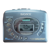
Related product manuals