15
XR-CA310/L210
TAPE DECK SECTION 0 dB= 0.775 V
1. The adjustments should be performed in the order given in
this service manual.
2. The adjustments should be performed for both L-CH and
R-CH.
Test Tape
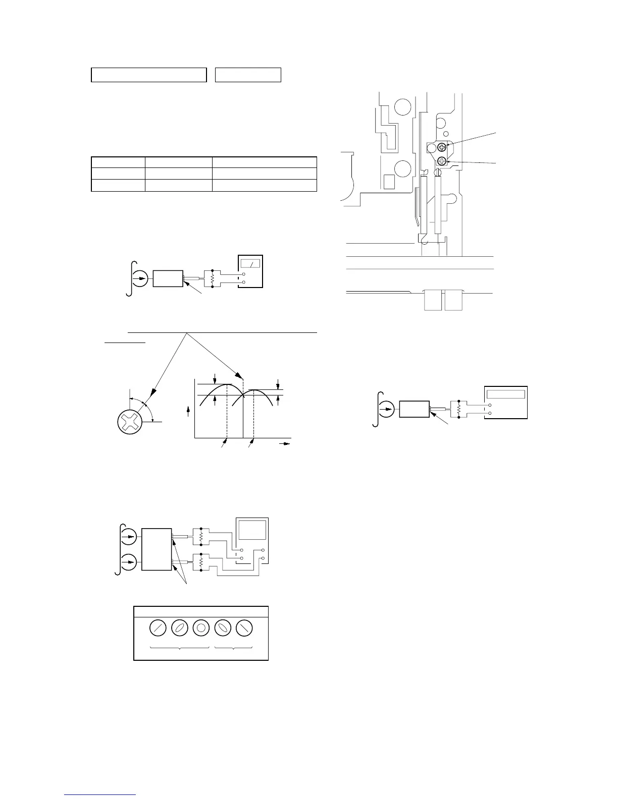
PB Head Azimuth Adjustment
Procedure:
1. Put the set into the FWD PB mode.
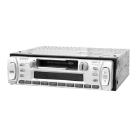
2. Turn the screw and check the output peak value. Adjust the
screw so that the peak value in channels L and R coincides
within 3 dB.
3. Check the phase in the FWD PB mode.
4. Repeat the above adjustment for the REV PB mode.
5. Check that output level difference between FWD PB mode
and REV PB mode is within 4 dB.
Type Signal Used for
P-4-A063 6.3 kHz, –10 dB head azimuth adjustment
WS-48A 3 kHz, 0 dB tape speed adjustment
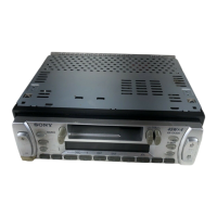
Adjustment Location: PB head
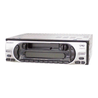
Tape Speed Adjustment
Setting:
Procedure:
1. Put the set into the FWD PB mode.
2. Adjust adjustment resistor for inside capstan motor so that the
reading on the frequency counter becomes in 3,015 Hz.
Specified Value: 2,940 to 3,090 Hz
Adjustment Location: See page 18.
level
meter
test tape
P-4-A063
(6.3 kHz, –10 dB)
set
speaker out terminal
4 Ω
+
–
screw
position
L-CH
peak
within
3 dB
output
level
L-CH
peak
R-CH
peak
within
3 dB
angl