19
Sookook Corporation
2C. Damper Motor Setting
This device enables the load operation automatically when the burner is running. The shaft of this motor is connected to the air damper and
gas butterfly valve through linkage device for simultaneous operation.
Damper Motor of HIGH/LOW Control Burner
PROGRESSIVE HIGH/LOW, PROPORTIONAL Damper Motor
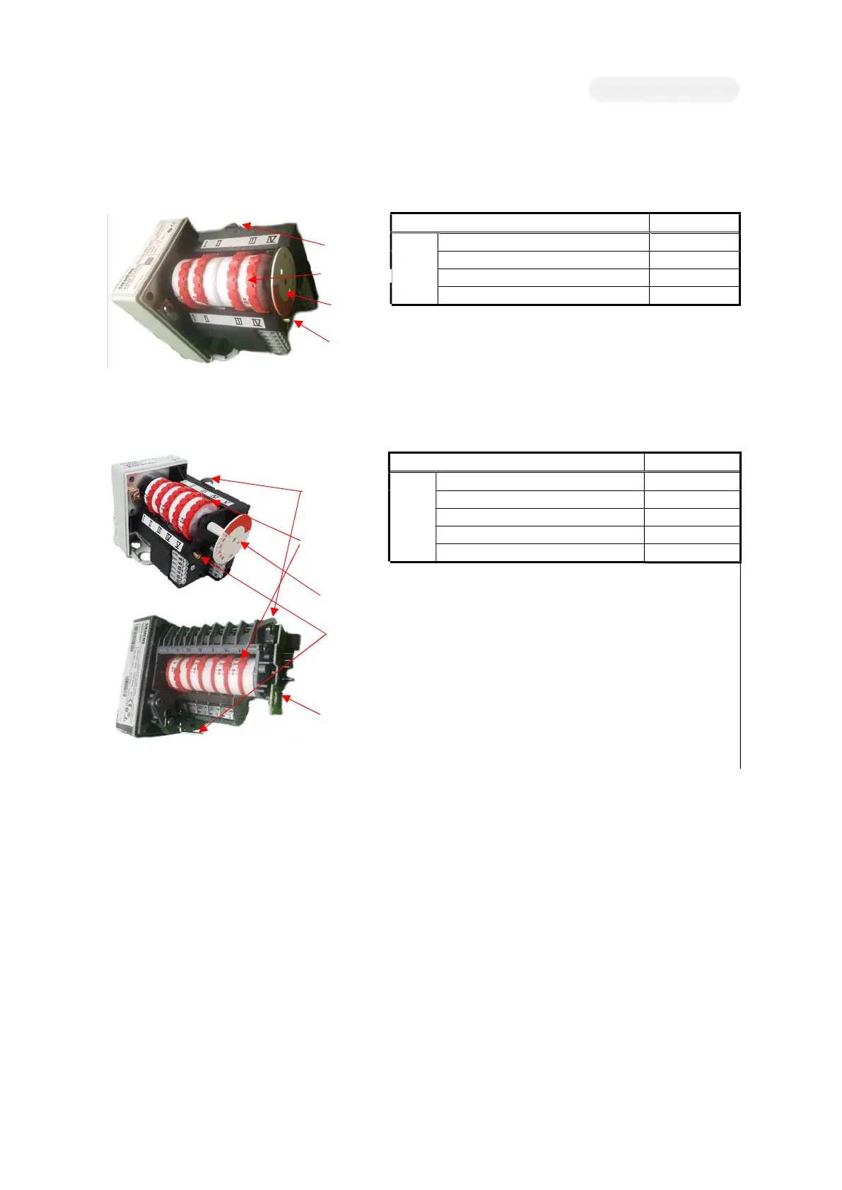
[Figure2 C-B. SQN30.402 Damper Motor]
[Figure2 C-C. SQM10 Damper Motor]
Description Damper Motor
Setting
HIGH ⅠCAM
LOW ⅡCAM
IGNITION ⅢCAM
LIMIT for Preventing Ignition at HIGH ⅣCAM
LIMIT for LEAK CHECK ⅤCAM
CAM Factory Setting.
Ⅰ(90˚), Ⅱ(0˚), Ⅲ(15˚), Ⅳ(20˚), Ⅴ(50˚)
Following orders shall be kept when adjusting cam angle at site.
ⅠCAM > ⅤCAM > ⅣCAM > ⅢCAM > ⅡCAM
If the CAM angle order is not maintained as above, it will case a
malfunction.
Feedback potentiometer is applied to check damper position for
proportional control.
The damper motor opens clockwise when viewed from behind.
The role of each cam is as the top right figure, and each cam can be easily changed by using the cam adjusting device. The setting angle of
the cam is the same as the position indicated by the protrusion on the side of the cam.
All damper motors have an automatic/manual switching lever. If you change to manual mode (press to fix or flip sideways), you can easily
check the opening angles of the air damper and gas butterfly valve at set position of each cam. The angle of the damper motor can be checked
with the angle indicator. (Manual switching is dangerous when the burner is running. Please do it at the stop state.)
If the angle is set too higher than the mechanical limit angle of the linkage device in the high combustion position, the damper motor will
continuously operate to reach the setting position, but the actual air damper will no longer open mechanically. Please note that motor damage
may occur due to the overload of the damper motor coil in this case.
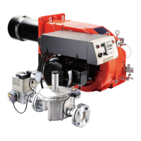
[Figure2 C-A. SQN30.111 Damper Motor]
Description SQN 30.111
Setting
HIGH ⅠCAM
IGNITION / LOW ⅡCAM
LIMIT for LEAK CHECK ⅢCAM
LIMIT for Preventing Ignition at HIGH ⅣCAM
CAM Factory Setting.
Ⅰ(30˚), Ⅱ(10˚), Ⅲ(25˚), Ⅳ(15˚)
Following orders shall be kept when adjusting cam angle at site.
ⅠCAM > ⅢCAM > ⅣCAM > ⅡCAM
If the CAM angle order is not maintained as above, it will cause a
malfunction. .
Cam Adjuster
C
Damper Motor
Angle
Feedback
Potentionmeter
Auto/Manual
Lever
Cam Adjuster
C
Damper Motor
Angle Indicator
Auto/Manual
Lever