26
Sookook Corporation
2G. Combustion Air Flow Control
Air Damper
An air damper is installed near the inlet to properly inflow the combustion air suitable for consumption during load operation, and it works in
conjunction with a damper motor and a linkage device.
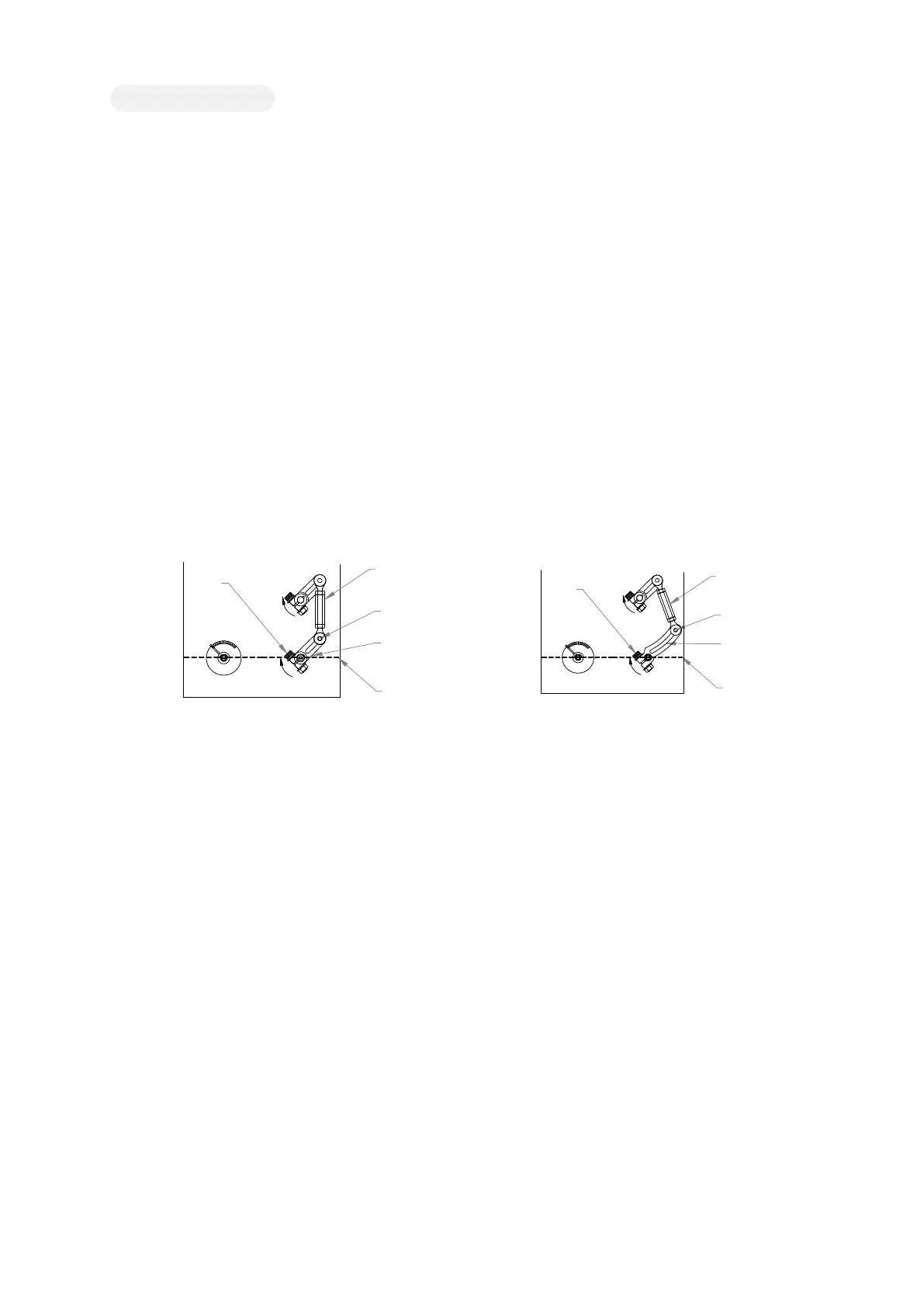
How to Adjust Air Flow of HIGH/LOW Control Burner
- Air flow control at low combustion mode
If you slightly loosen the bolt fixing the air damper shaft (VB) shown in Figure 2G-A, you can turn the damper plate (S) with your hand, Hold
the linkage device with one hand and hold the damper plate with the other hand, move the damper to the angle with proper air flow and
tighten the bolt again. (Turn clockwise seen from behind the burner to increase the air flow and counter clockwise to decrease the air flow.)
You can also adjust the air flow by changing the angle of the low combustion positioning cam (cam II, See Figure 2C-A) in the damper motor
But, it is not recommended because the air damper and gas butterfly valve is connected through the linkage device and air flow and gas flow
change at the same time.
- Air flow control at high combustion mode
Air flow at high combustion mode shall be adjusted by angle of the high combustion positioning cam (cam I, See Figure 2C-A) in the damper
motor. At this time, the gas flow is changed as well. To adjust the gas flow, adjust the gas flow control device V1 of the gas solenoid valve
(See 2F, gas flow control). (If the structure can change the length of the linkage device, it is recommended to adjust the link length. In this
case, the butterfly valve is fixed and the adjusted gas flow does not change.)
How to Adjust the Air Flow of Progressive HIGH/LOW, Proportional Control Burners
To regulate the air flow in the ignition position, slightly loosen the bolt fixing the air damper shaft (VB) shown in Figure 2G-B and hold the
link device (sector regulator) with one hand and hold the damper plate with the other hand. Move the damper to the desired position and
tighten the bold again. (Turn clockwise seen from behind the burner to increase the air flow and counter clockwise to decrease the air flow.)
Or properly adjust the angle of the ignition positioning cam (cam III, see Figure 2C-B).
To adjust the air flow in the low combustion position, adjust the angle of the low combustion positioning cam (cam II, see Figure 2C-B).
To adjust the air flow in the high combustion position, adjust the angle of the high combustion positioning cam (cam I, see Figure 2C-B). If
there is a lack of air at the maximum combustion, slightly loosen the bolt RA shown in Figure 2G-B, and then move the tie rod T along guide
CT to increase/decrease air flow. This will move the damper S to achieve the desired air supply. If the RA moves away from the air damper
shaft, the air flow decreases and if it approaches, the air flow increases.
After adjusting the air flow, please check the air-fuel ratio again.
Note : After adjusting, make sure the RA bolt and VB screw are tightly closed.
[Figure 2G-A. HIGH/LOW] [Figure 2G-B. PROGRESSIVE HIGH/LOW, PROPORTIONAL]
9
0
°
6
0
°
3
0
°
0
°
S
T
VB
CT
RA
S
T
VB
CT
RA
9
0
°
60
°
30
°
0
°