Advanced Operation DLM-E 3kW & 4kW Series Power Supplies
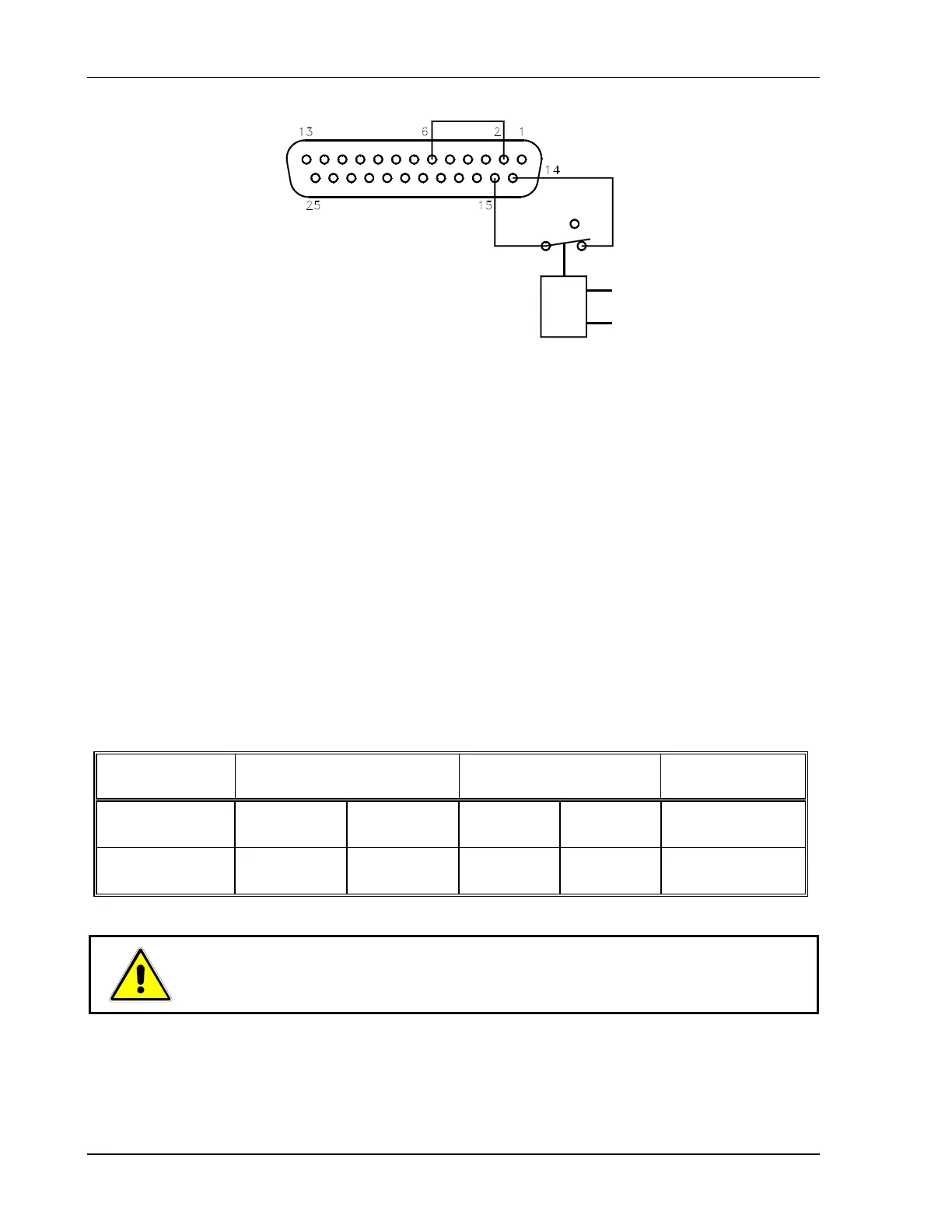
Figure 4–16.
Using Shutdown with Contact Closure of Normally CLOSED Relay (S1-6 Down)
4.6 Remote Monitoring
4.6.1 Readback Signals
Calibrated readback signals for remote monitoring of the output voltage and current are
available via connections at the J3 connector on the rear panel. Rear panel DIP switch S1
settings allow you to select either a 0–5 VDC or a 0–10 VDC range for the output. See
Section 4.2 Configuring for Remote Programming, Sensing, and Monitoring for more information
about making these connections.
The following table shows the required pin connections and switch settings for remote
monitoring of readback signals with 0–5 VDC or 0–10 VDC outputs. Use shielded–twisted pair
wiring (20 to 24 AWG) and ground the shield to J3 connector pin 6 or to the chassis via one of
the J3 connector screws. The readback signal represents 0 to 100% of the model–rated
output.
Readback
Signal
J3 Connections
Signal (+) Return (–)
Switch S1 Settings
Switch # Setting
Output Signal:
Range
Voltage Monitor Pin 19 Pin 12 S1–4
UP
DOWN
0–5 VDC
0–10 VDC
Current Monitor Pin 7 Pin 12 S1–5
UP
DOWN
0–5 VDC
0–10 VDC
CAUTION!
Always remove J3 mating connector from supply before soldering.
4-20 M362000-01 Rev E