V. Wiring
A. Wiring Controller
Wiring PixiePro to Control a Single Device
Attention! Remove power from the IR emitter
before wiring to PixiePro. DoNOTattemptto
connectthewirestothePixieProwhileitispow-
ered. Doingsomaydamagetheunit.
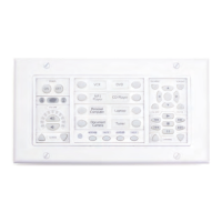
Connectthethree-conductorcabletothecaptive-
screwconnectoronthebackofthePixiePro.Be
surethatthewiresagreewiththeconnectionson
thecableassemblyblockend(diagrambelow).
Note:Theoutputpositionlabeled RS232TX and
thefemaleRJ45portonthePixieProarefor
futureusewithotherSPControlshardware.
Wiring PixiePro to Control Multiple Devices
ThePixieProshipswithjustoneIRemitter;each
additionaldevicethatthePixieProcontrolswill
requireanadditionalIRemitter(notincluded,part
no.PXE-EMIT).
Note:ThePixiePromaybeusedtodriveamaximumofsixIRemitterswithasinglepowersupply.
Todrivemorethansix,additionalpowersuppliesmustbeordered(partno.PXE-DCM-PS).
AllthreewiresofthePixieProoutputmustbewiredinparalleltoeachemitterthatwillcontrola
device.ThecableassemblyblocksmaybewiredinastarpatternoutfromthebackofthePixiePro,
ordaisy-chainedfromoneassemblyblocktothenext,usewhichevermethodrequirestheleasttotal
linelength.
Foradiagramofdaisy-chainedwiringbetweentwoIRemitters,seeFigure 9 onpage8.
B. Wiring IR Emitter
Wiring IR Emitter to Control a Single Device
WiretheemitterblocktothePixieProusingthree-conductorwire
(notincluded).SPControlsrecommendsusing18-or20-gauge
wire.Standardaudiocablewillwork(e.g.,Belden™8451
or9451).
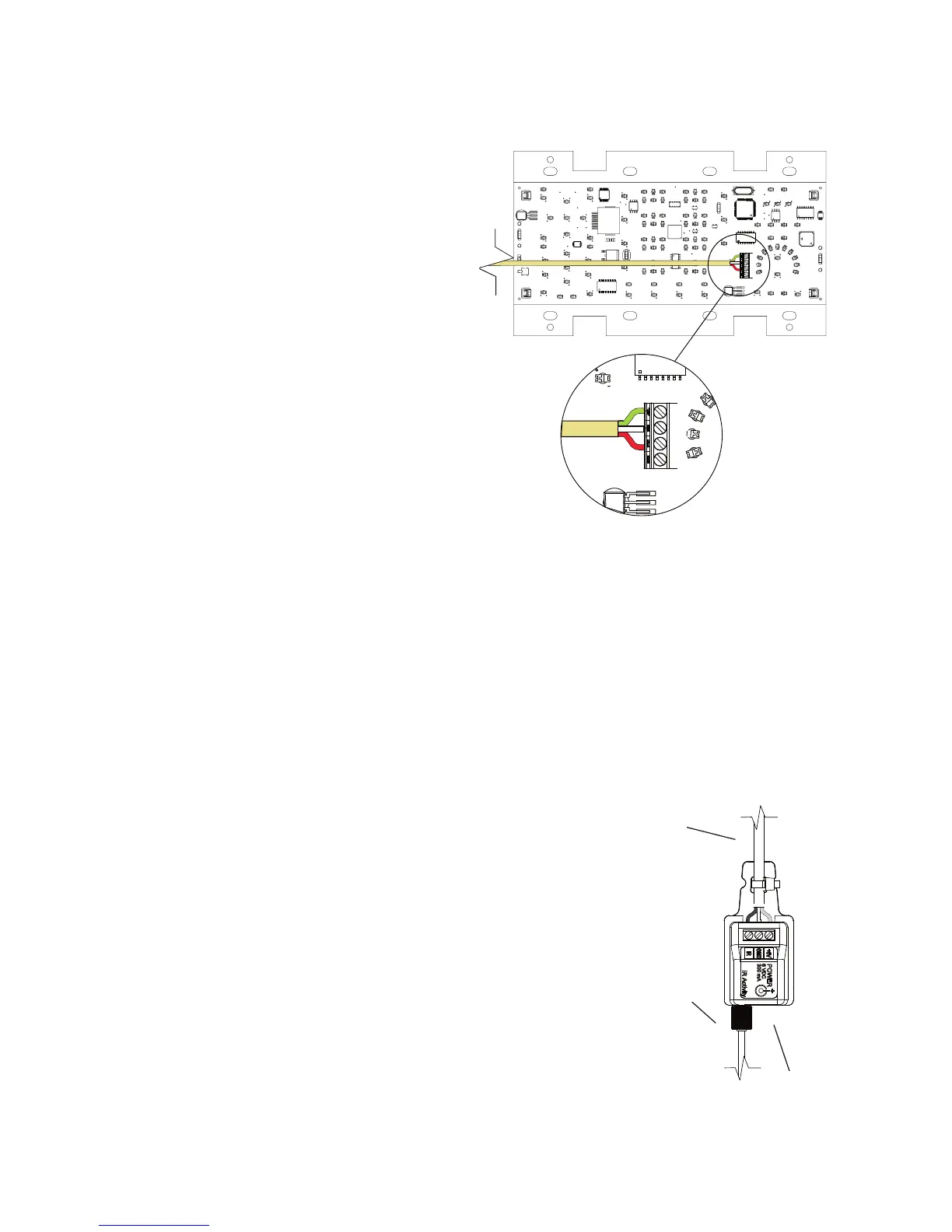
1. Wire Cable Assembly. Connectthethree-conductorcabletothe
screwdownpostsinthecableassemblyblock.Thethreepositions
onthecableassemblyblockarelabeled+6V,GND,andIR.Match
theconductorstothecorrespondingpositionsonthecaptivescrew
connectoronthebackofthePixiePro.