SC-CF-SBD Owner’s Manual26
Output Configuration
Blower
Configuration of
the blower
1) Locate the Pump 2
connectors.
(P6, P11 & P9 for a 120V pump)
(P6, P11 & P17 for a 240V pump)
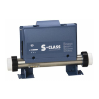
2) Using a pair of long-nose
pliers, unplug all three
wires from the connectors
on the board.
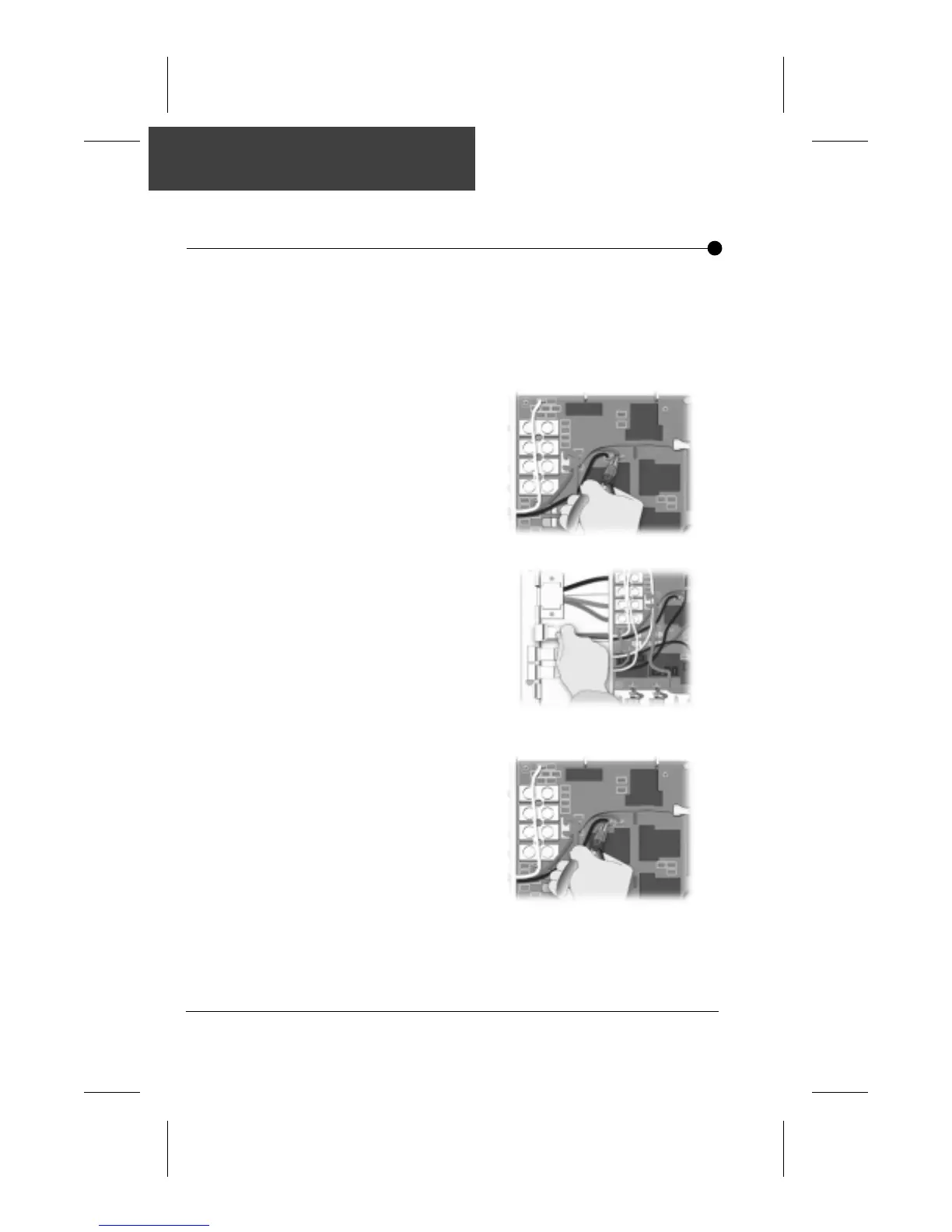
3) Remove the J&J Pump 2
connector by sliding it from
its slot on the pack.
4) Put the J&J Blower
connector (included with
your pack) in place and
slide the wire through the
hole of the interior panel.
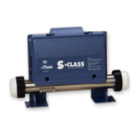
5) Reconnect the three wires
on the board at the follow-
ing locations
Black= P11
Green= P6
White= P9 for a 120V
blower
P17 for a 240V
blower
Make sure they are properly inserted.
If you purchased a pack with J & J connectors and your spa is
equipped with a blower, you need to replace the factory
installed J&J pump 2 connector with the supplied J&J blower
connector.
To do so: