Page 17 of 25
3.4 INSTALLING THE CABLE ROUTING COVER PLATE
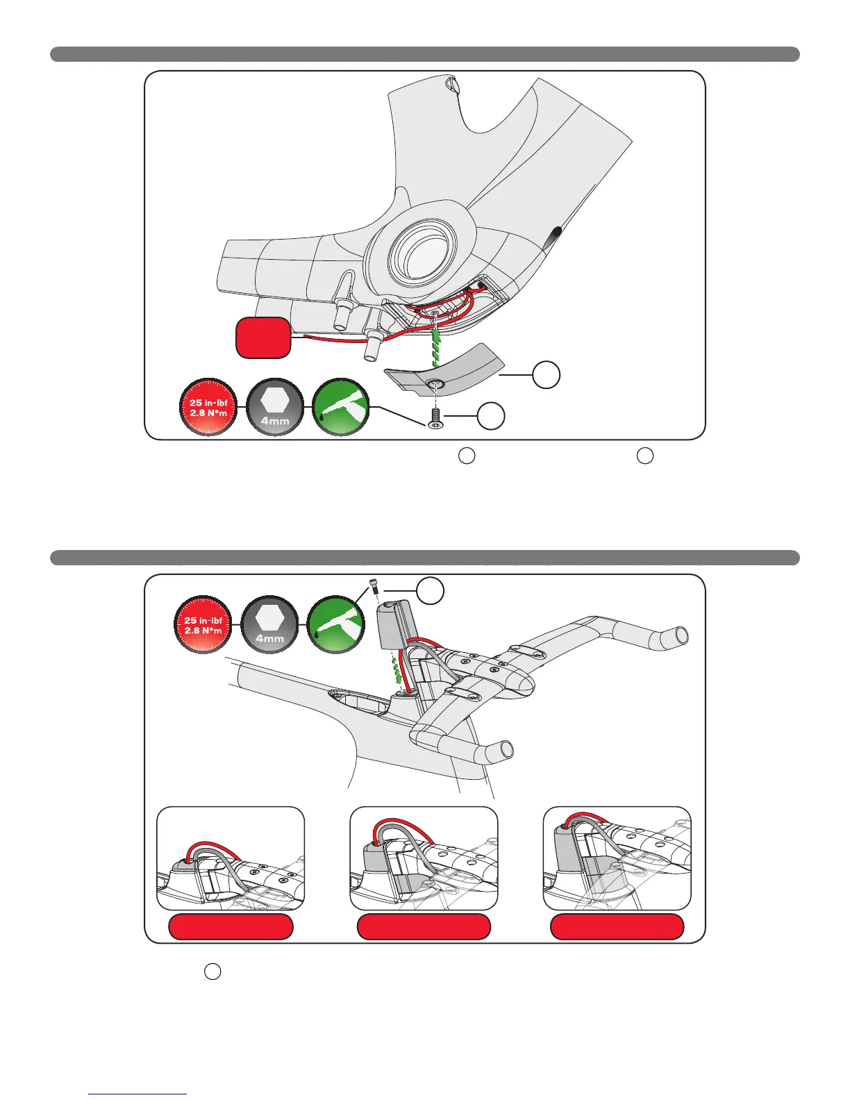
10. Once the wiring or cable housing is routed, install the cable routing cover plate
E
, followed by the cover plate bolt
F
(M6x15mm, 3mm
countersunk Allen hex head).
11. Torque the bolt to 25 in-lbf (2.8 N*m).
3.5 INSTALLING THE CABLE ROUTING CONTROL TOWER
12. Once the bike fit has been finalized, choose the Control Tower that corresponds to the final amount of spacers. Attach the Control Tower to the
frame using the tower bolt
G
(M5x20mm, 4mm Allen hex head).
13. Torque the bolt to 25 in-lbf (2.8 N*m).
E
F
G
Small tower, no spacer Medium tower, 1 spacer Large tower, 2 spacers
To
battery