20
R
EFERENCE
& I
NSTALLATION
M
ANUAL
PART 5: ZONE PROGRAMMING
When programming zones, the zone assignment is dependent on where the detection devices are connected (see Table 4).
Note: In the 1725EX zone 5 does not exist. In the 1725 zones 5 and 10 do not exist.
What is an Expansion Input?
There are a total of eight expansion inputs available. Each hardwired input on a Zone Expansion Module or wireless transmitter
used by the Liberator Wireless Bus Module can be assigned to an expansion input. The expansion inputs can be used in any
combination. For example, you can assign four wireless transmitters as well as 4 hardwire inputs to the expansion inputs.
Regardless of how many expansion modules are being used, the control panel cannot support more than eight expansion
inputs. The expansion module inputs are assigned as follows:
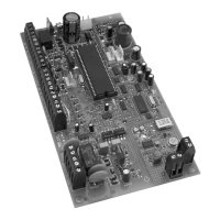
SPC-319 Liberator Wireless Bus Module
Wireless transmitters assigned to sections [601] to [608] of the control panel represent expansion inputs 1 to 8 respectively.
For more information, please refer to Wireless Transmitter Assignment on page 47.
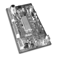
SPC-ZX4 and ZX8 Zone Expansion Module
Detection devices connected to input terminals Z1 to Z4 of the SPC-ZX4 module or Z1 to Z8 of the ZX8 module, represent
expansion inputs 1 to 8 respectively. Please note that the module’s inputs must be enabled in section [651] of the control
panel. For more information, please refer to Zone Input Assignment on page 50.
Do not assign inputs from different modules to the same expansion input. For example, do not assign a
wireless transmitter to section [601], then connect a detection device to input Z1 of the ZX8 and enable
option [1] in section [651].
After connecting a hardwired detection device to one of the control panel's or zone expansion module’s input terminals or
after setting up any wireless transmitters, you must define the associated zone's parameters. The Zone Parameters define
the type of zone, the zone's partition assignment and how the control panel will react when an alarm condition occurs on that
zone as described in the following sections. These Zone Parameters are programmed into one section as detailed in Figure
5-1 (see next page). For more information on the Installation of detection devices to the control panel and its expansion
modules, please refer to page 7.
Table 4:
Zone Recognition Table
Device connected to
which input?
1725EX 1725 1728EX 1728
1758EX 1758
NO ATZ WITH ATZ NO ATZ WITH ATZ
Control Panel Input 1 = Zone 1 Zone 1 & 6* Zone 1 Zone 1 & 6
Control Panel Input 2 = Zone 2 Zone 2 & 7 Zone 2 Zone 2 & 7
Control Panel Input 3 = Zone 3 Zone 3 & 8 Zone 3 Zone 3 & 8
Control Panel Input 4 = Zone 4 Zone 4 & 9 Zone 4 Zone 4 & 9
Control Panel Input 5 = N/A N/A Zone 5 Zone 5 & 10
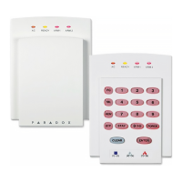
Keypad Zone 1 = Zone 6* Zone 11* Zone 6 Zone 11
Keypad Zone 2 = Zone 7 Zone 12 Zone 7 Zone 12
Expansion Input 1 = Zone 8 Zone 13 Zone 8 Zone 13
Expansion Input 2 = Zone 9 Zone 14 Zone 9 Zone 14
Expansion Input 3 = Zone 10 Zone 15 Zone 10 Zone 15
Expansion Input 4 = Zone 11 Zone 16 Zone 11 Zone 16
Expansion Input 5 = Zone 12 N/A Zone 12 N/A
Expansion Input 6 = Zone 13 N/A Zone 13 N/A
Expansion Input 7 = Zone 14 N/A Zone 14 N/A
Expansion Input 8 = Zone 15 N/A Zone 15 N/A