IM-P343-44 CTLS Issue 5 11
EP500 Standard Electropneumatic Positioner
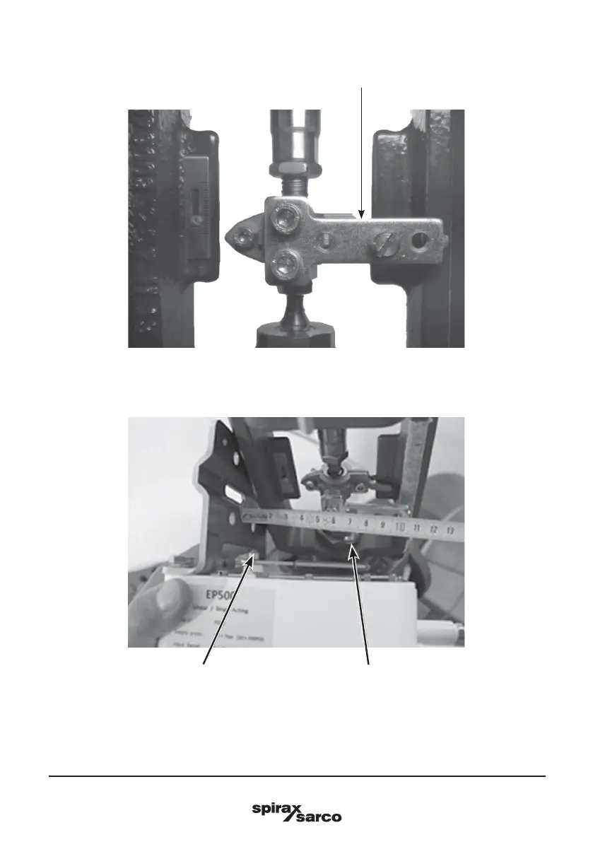
Step 2
Using the 2 off M6 pan head screws, securely attach the 'T' shaped sliding pin holder to the
valve actuator coupling block (Figure 6).
Depending on the travel of the valve actuator and depending on the actuator yoke, apply a
medium strength thread locker to the sliding pin and screw into the correct hole on the sliding
pin holder and tighten. Use Figure 7 and Table 1 to determine the correct hole to use.
Fig. 6
Fig. 7
Feedback lever fulcrum Pin