IM-P337- 6 9 EMM Issue 2
26
+
-
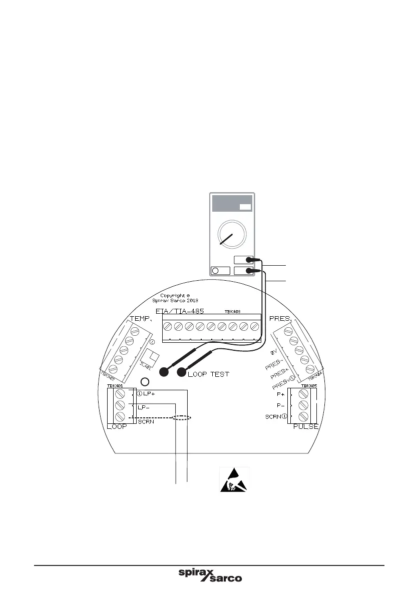
Testing the 4-20mA loop current:
The 4-20mA loop current can be tested without having to disconnecting the wiring. This enables the user to
verify the correct signal is being transmitted for the corresponding flow rate, for fault finding and for calibrating
the 4 and 20mA output signal. Simple connect a Digital Multimeter (DMM) across the “LOOP TEST” terminals
(TBK401) whilst the MVT10 is powered up. The DMM does not affect or interfere with the transmitted signal.
For calibrating or fault finding, selected the commissioning menu using the MVT10 front keypad. Use “Output
/ 4-20mA / Check 4mA or 20mA” to calibrate the 4-20mA signal and “Test – 4-20mA Out” set the loop to a
value between 4 and 22mA to aid in fault finding. See section 7.
Digital Multimeter settings:
Connect the test leads to DMM’s “mA” or “A” terminal (if applicable).
Select the appropriate dc current range, to measure 4-20mA accurately.
With the MVT10 powered, connect the DMM test leads to the “LOOP TEST” terminals, ensuring the correct
polarity.
Note: If the DMM reads zero, recheck the setting above and check the internal fuse in the DMM itself has
not blown.
Fig. 21 4-20 mA loop power wiring - testing
4-20mA
LOOP
mA
mA
COM
OFF
mA
V
Black
Red