IM-P337- 6 9 EMM Issue 2
37
temp
imp
total
f
power
pres
low
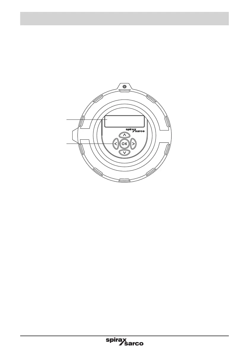
All commissioning of the MVT10 is carried out through the housing end screw caps. Power and
communication connections (termination board) are accessed through the rear screw cap and
configuration commissioning is done via the display keypad accessed through the front screw cap (with
glass). The display assembly consists of a small LCD display and a five button key pad.
As all commissioning settings are stored in a non-volatile memory. If using the MVT10 for a superheated
steam application (with a temperature sensor), the sensor must be connected before powering up the
MVT10. Otherwise the pressure channel calibration will be affected. A M750 display unit can be used to
provide a remote display function if required.
After all mechanical and electrical work has been completed, the following commissioning instructions
should be followed.
The MVT10 should be commissioned with the flow through the ILVA20 isolated.
The MVT10 can not be used with ILVA or Gilflo products, as they are sold paired with a ILVA20.
Note: The MVT10 is factory set to display data in metric units. To commission the MVT10 to display imperial
units see Section 7.3.2.
LCD display
5 button keypad
Fig. 27 MVT10 Display
7. MVT10 and menu structure