EasyManuals Logo

Spirax Sarco LC2610 User Manual

Spirax Sarco LC2610
40 pages
To Next Page IconTo Next Page
To Previous Page IconTo Previous Page
Page #17 background imageLoading...
Page #17 background image
IM-P402-93 AB Issue 7
17
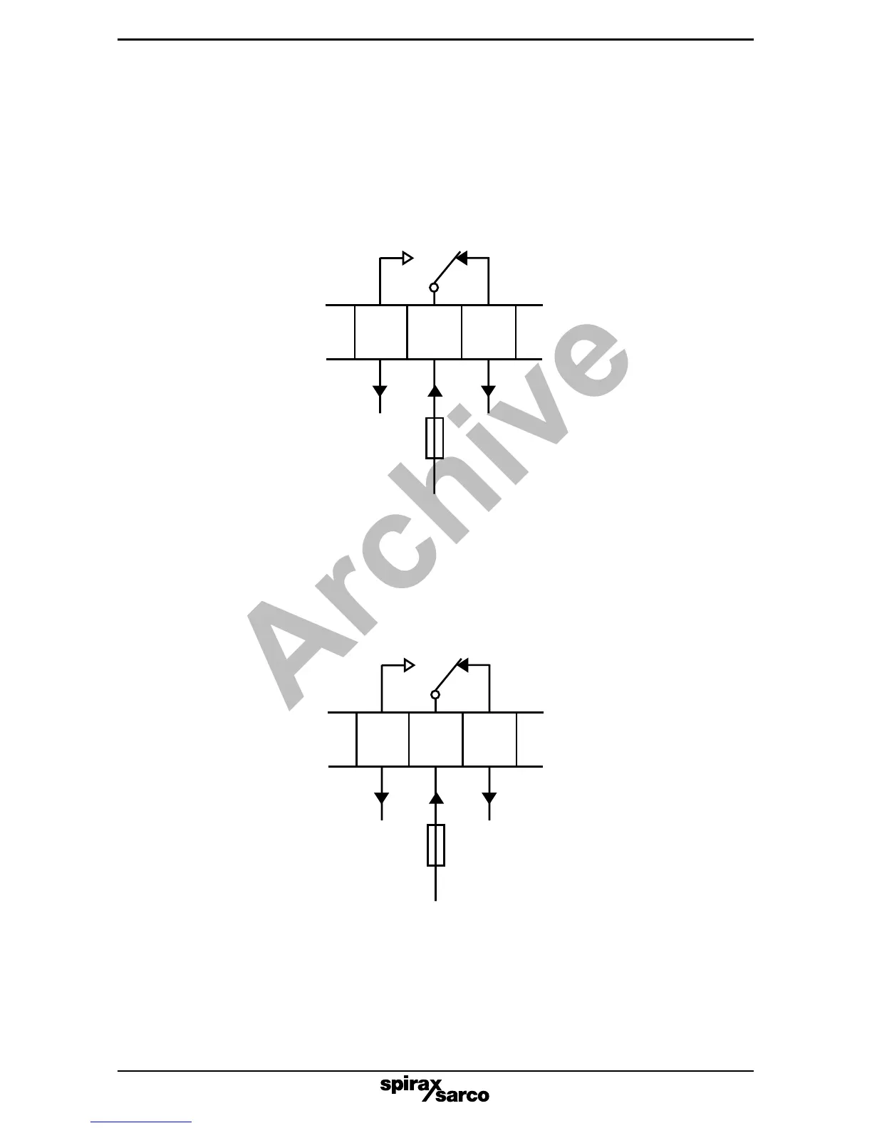
6.10 Alarm relays (All relays shown in the power off position)
Figures 17 and 18 are typical alarm circuit wiring diagrams.
The fuse rating must not exceed 3 A.
Controller and all relay mains supplies must be on the same phase.
High
Normal Alarm
10 11 12
Burner circuit broken at alarm To alarm lamp or bell
3 A maximum
Relay supply
Low
Normal Alarm
13 14 15
Burner circuit broken at alarm To alarm lamp or bell
3 A maximum
Relay supply
Fig. 17
Fig. 18
Archive

Questions and Answers:

Question and Answer IconNeed help?

Do you have a question about the Spirax Sarco LC2610 and is the answer not in the manual?

Spirax Sarco LC2610 Specifications

General IconGeneral
BrandSpirax Sarco
ModelLC2610
CategoryController
LanguageEnglish

Related product manuals