IM-P402-93 AB Issue 7
9
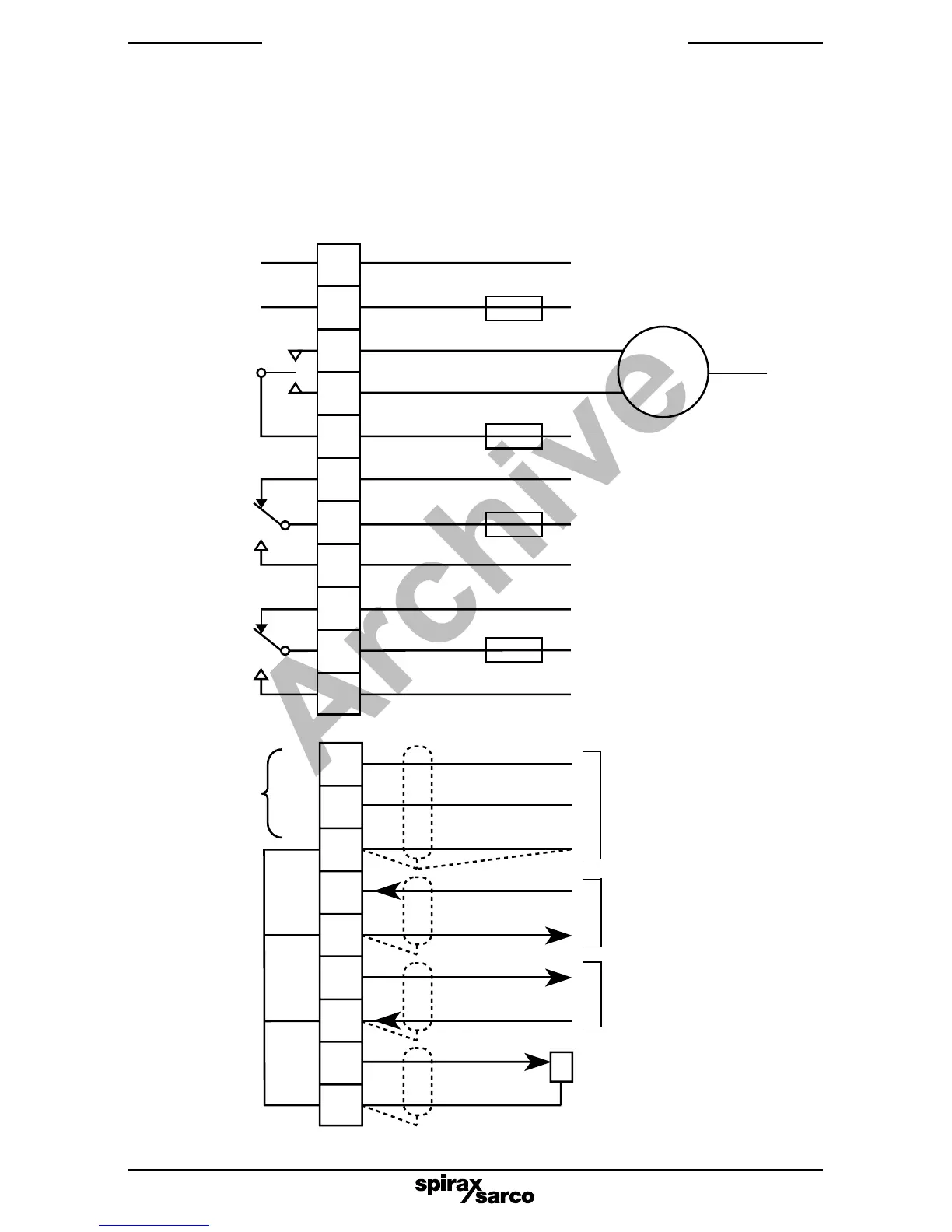
Note:
Terminals
1, 3, 5 and 7
are common.
See CAUTION,
Section 6.3.
Closed
4 - 20 mA transmitter output*
4 - 20 mA steam meter input*
(optional)
Open
Potentiometer input (1 k ohm)
or water flowmeter*
Capacitance probe or 4 - 20
mA input.
Do not connect terminals 1,
3, 5 or 7 to earth or ground
except via the probe body.
Ensure resistance from probe
body to pipework/boiler shell
is less than 1 W.
Fig. 7
* These units must be isolated from earth.
Input
Level input
+
9
8
7
6
5
4
3
2
1
6. Electrical installation
and wiring diagrams
6.1 General wiring diagram (All relays shown in the power off position)
Note:
It is essential to select the correct sensitivity on the PA20 preamplifier, (see the PA20
Installation and Maintenance Instructions for details). Tighten the terminals to 0.8 N m
(7 lbf in).
High relay alarm
Low relay alarm
Control
relay
Select
voltage
internally
Normal
Relay supply
Alarm
Normal
Relay supply
Relay supply
Alarm
Close
Open
N
N
L
Mains
Control valve electric
actuator (valve
motor drive)
20
19
18
17
16
15
14
13
12
11
10
3 A max.
3 A max.
3 A max.
3 A max.