IM-P736-02 EMM Issue 3
54
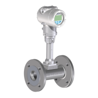
VLM30 In-Line Vortex Flowmeter
4.5 Power Supply Power-Up
-
Switch on the device power supply.
After switching on the power supply, the system data in the SensorMemory is compared with the
values stored internally in the transmitter.
-
If the system data is not identical, it is matched automatically.
-
The flowmeter is now ready for operation.
-
The LCD display shows the process display.
4.6 Checks after switching on the power supply
The following must be checked after commissioning the device:
-
Parameter configuration must correspond to the operating conditions.
-
The system zero point is stable.
If this is not the case, a zero point balance must be carried out (see Section 5.12 Zero point balance
under operating conditions).
4.7 Checking and configuring the basic settings
The device can be factory parameterised to customer specifications upon request. If no customer information
is available, the device is delivered with factory settings.
Parameter Factory setting
Active Mode Liquid Volume
Output Value Flow rate
DO Function No function
Q
max
Actual value set to Q
max
DN.Depending on the nominal diameter of the flowmeter.
Unit Q m³/h
Analog In Value No function
HART In Value No function
Low Flow Cutoff 4%
Iout at Alarm Low Alarm Value
Low Alarm Value 3.55 mA
High Alarm Value 22 mA

 Loading...