IM-P736-02 EMM Issue 3
36
VLM30 In-Line Vortex Flowmeter
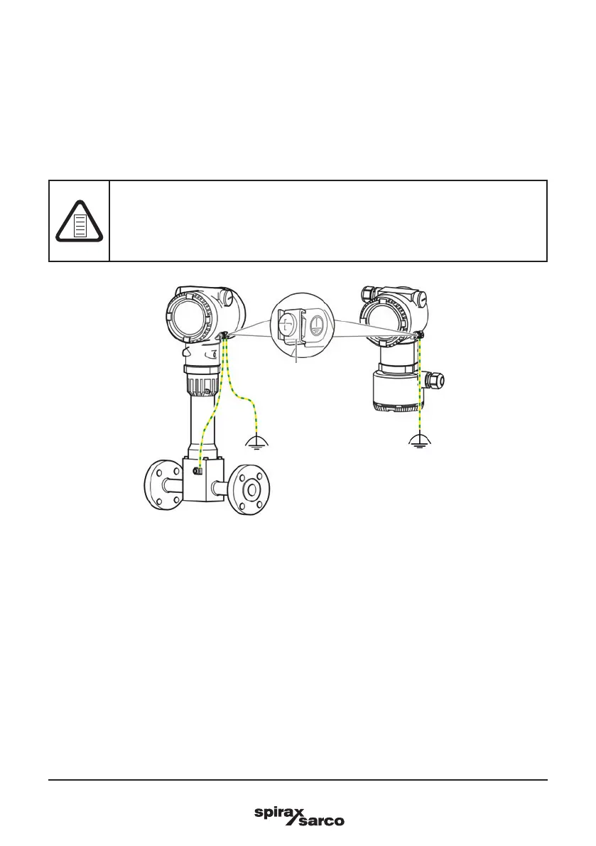
Fig. 20 Ground Terminals
For the earthing (PE) of the transmitter or the connection of a protective earth, a connection is available both
on the exterior of the housing and in the connection space. Both connections must be galvanically connected
to one another. To avoid potential differences, a 3-point grounding as shown in Figure 20 is recommended.
These connection points can be used if grounding or the connection of a protective conductor is prescribed
by national regulations for the selected type of supply or the type of protection used.
-
Loosen the screw terminal on the transmitter housing or on the housing of the VLM30.
-
Insert the forked cable lug for functional grounding between the two metal tabs and into the loosened
terminal.
-
Tighten the screw terminal.
3.16 Cable glands
We do not supply cable glands as standard as part of our strive towards sustainability.
Suitable glands or blanking plugs to fit either M20 x 1.5 or ½" NPT thread will need to be purchased
separately and used on the unit, as it will not meet it's IP rating if they are not fitted.
3.17 Grounding
NOTE
Impact on measurement
The measurement may be impacted by external electric disruptions (EMC disruptions).
- Ground the device as shown to avoid impact on the measurement by external electric
disruptions (EMC disruptions).
Integral mount design
and sensor in remote
design
Transmitter with remote
mount design
Ground
terminal