Shenzhen Sincevision Technology Co.Ltd
www.cnsszn.com
15
/
43
Quick Start Guide of SR Series ©2021 SSZN All Right Reserved
6.1.4 Cautions for wiring
1. Terminal connection must not be live operation, do not supply power to the controller, and ensure that the
PLC, servo driver, etc. are in power off status. Hot plug terminal stage will cause controller damage.
2. 3-17 PIN are input ports, combined with PIN19 "COM_IN"; 21~36 PIN are output ports, combined with
20 feet "COM_OUT".
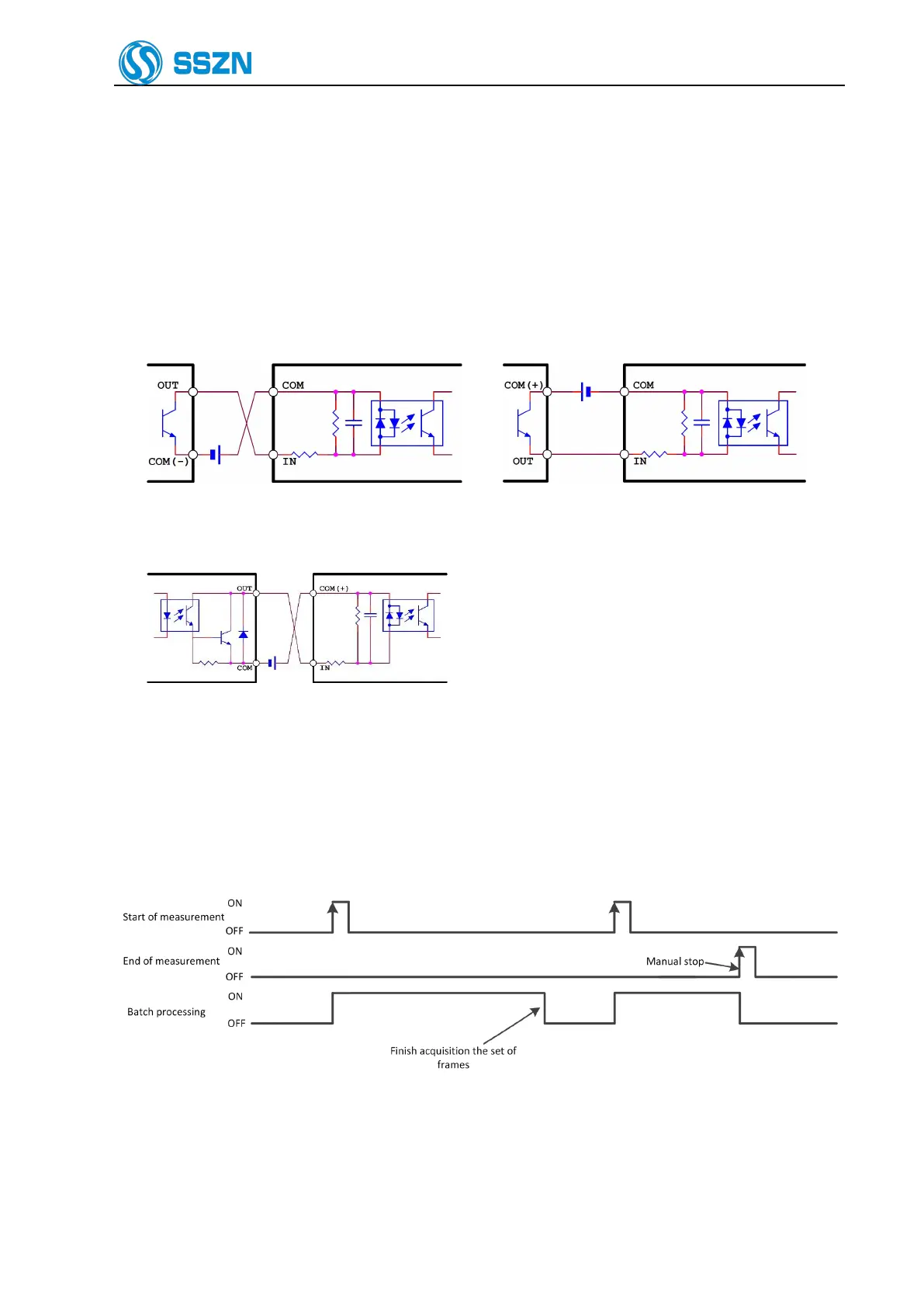
a) Input port and PIN19 wiring instructions:
PLC Leakage Output (NPN) Local Input Circuit PLC Source Output(PNP) Local Input Circuit
b) Output port and PIN20 connection instructions:
Local Output Circuit PLC Input Circuit(Positive Common End)
3. In the connection method using edge signal, PIN14 and PIN15 need to connect to 0V in order to avoid
triggering by mistake when they are not used.
4. When there is no input in PIN11, the start of measurement (PIN14) and end of measurement (PIN15) work
in edge mode. Figure 65 shows the time sequence diagram for signals.
Figure 6- 5 Time sequence diagram for Edge Mode
5. When there is a input signal in PIN11 all the time, the start of measurement (PIN14) works in level mode
and the end of measurement (PIN15) is invalid. Figure 6-6 shows the signal sequence diagram.