Shenzhen Sincevision Technology Co.Ltd
www.cnsszn.com
7
/
43
Quick Start Guide of SR Series ©2021 SSZN All Right Reserved
Please refer to “Hardware Manual of SR Series 3D Camera”.
24V power input
terminal block
Used for supply of the power source (DC24V).
Left: +24V, middle: 0V, right: Shell and GND
Ethernet port RJ45
connector
Connect to a personal computer or a switch with the Ethernet cable. (RJ-45
connector)
Connect to cameras with the camera cable, including camera-A connector
and camera-B connector.
Please refer to “6.2 Connecting the controller and the Camera”.
Do not use, or it will damage the controller
Showing the power
status, blue LED.
The controller is powered on normally
Power off, or the power supply is
abnormal.
Showing the controller
works status, green
LED.
The controller is in the normal
operation state.
Power off, or the controller
is abnormal.
Showing the controller
error status, red LED.
The controller is normal.
Support SR6000 and SR7000 Camera
Only support SR8000 Camera
4 Precautions for Mounting the Camera
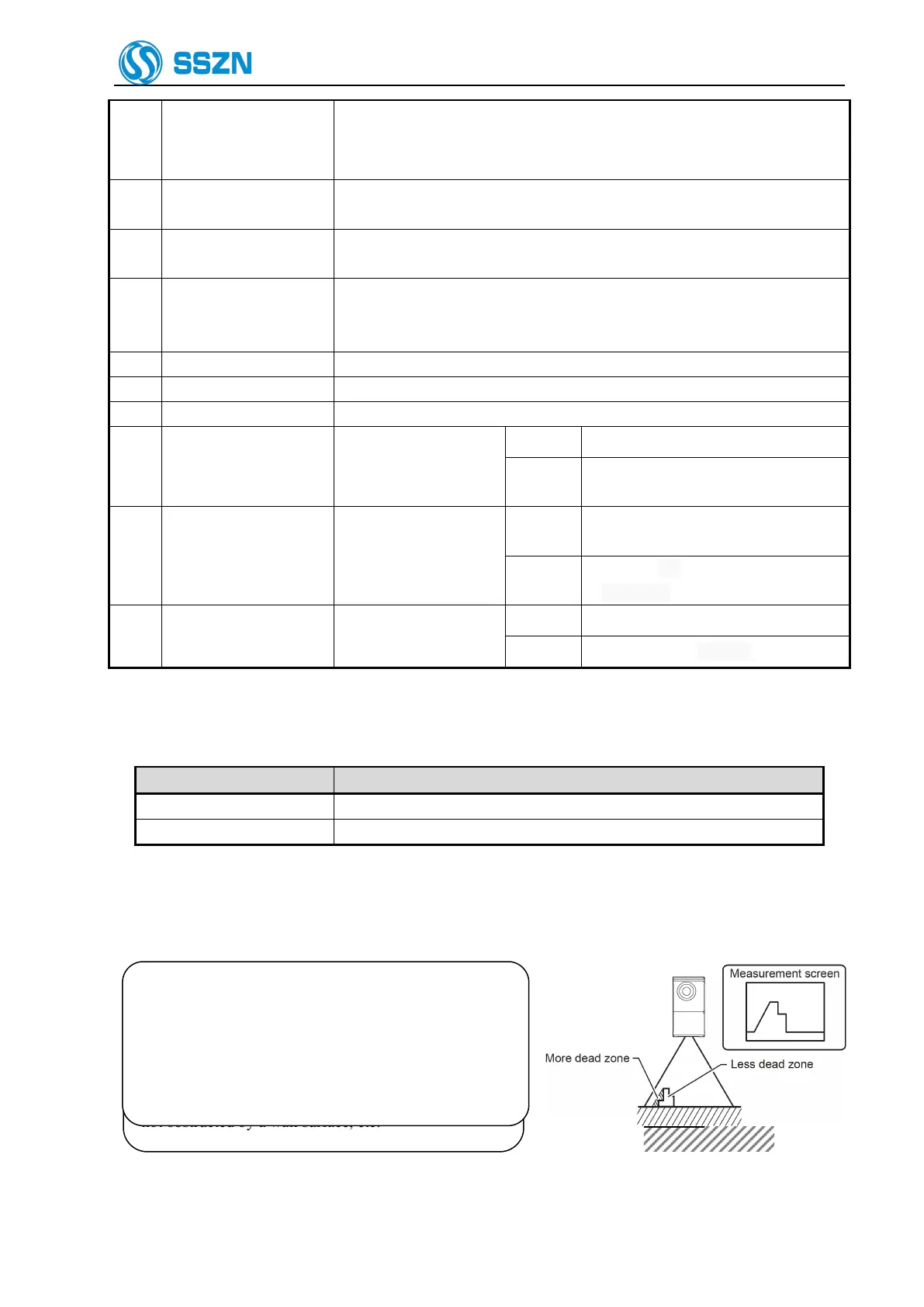
Figure 4- 1 Dead Zone Arises
When installing the camera, make sure that the laser
beam irradiating the target object and the laser beam
reflected from the target object into the receiver, are
not obstructed by a wall surface, etc.
Figure 4- 2 Laser Beam Optical Path Obstructed
Depending on their shape, some target objects create a
dead zone in the measurement range. Make sure that the
dead zone does not affect the measurement result.
This unit features a fan shaped laser beam and receiver
system. For this reason, the dead zone will be smaller
near the center of the X-axis measurement range.