Shenzhen Sincevision Technology Co.Ltd
www.cnsszn.com
5
/
43
Quick Start Guide of SR Series ©2021 SSZN All Right Reserved
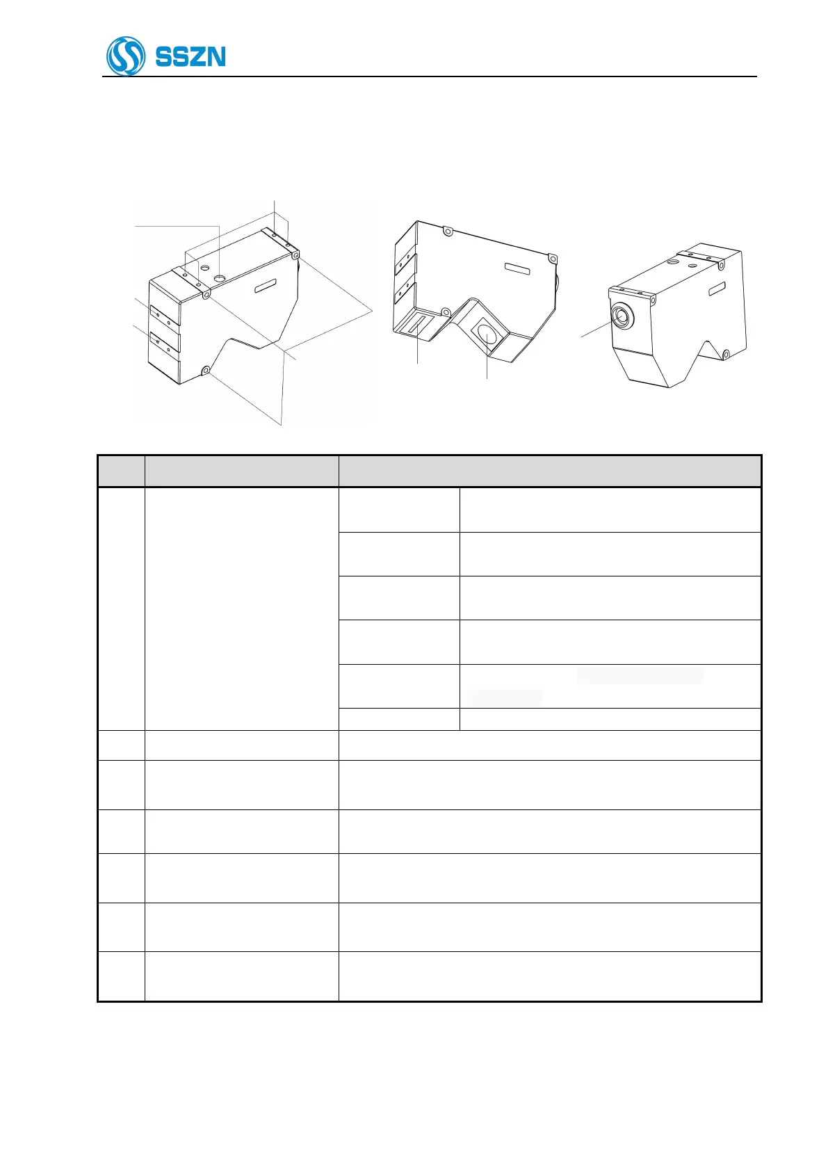
2.2 Description of Camera SR7000
The target object is at around the center of the Z
axis measurement area.
The target object is in the Z axis measurement
area.
The target object is out of the specified Z axis
measurement area.
Power off, or the power supply is failed
or abnormal.
Any system error occurred at the camera.
The screw holes can be used to mount the camera.
Use the hexagon socket bolt (included) to affix the camera.
Please refer to “4Precautions for Mounting the Camera”.
Mounting holes for the stray
light shield
Use the holes to mount a plate for blocking stray light. Do not use for
mounting the camera.
Receive the laser beam for measurement.
Protected by a glass cover.
Emit the laser beam for measurement.
Protected by a glass cover.
Connected with the camera cable.
Please refer to “6.2 Connecting the controller and the Camera”.