Shenzhen Sincevision Technology Co.Ltd
www.cnsszn.com
6
/
43
Quick Start Guide of SR Series ©2021 SSZN All Right Reserved
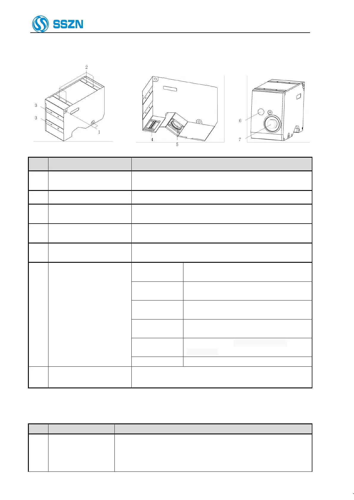
2.3 Description of Camera SR8000
Item Name Description
1 Mounting holes
Use the hexagon socket bolt (included) to affix the camera.
Please refer to “4Precautions for Mounting the Camera”.
2 Special mounting holes The screw holes can be used to mount the camera.
3
Mounting holes for the stray
light shield
Use the holes to mount a plate for blocking stray light. Do not use for
mounting the camera.
4 Sensor (transmitter)
Emit the laser beam for measurement.
Protected by a glass cover.
5 Sensor (receiver)
Receive the laser beam for measurement.
Protected by a glass cover.
6 Laser-emitting LED
Lights green
The target object is at around the center of the Z
axis measurement area.
Lights orange
The target object is in the Z axis measurement
area.
Blinks orange
The target object is out of the specified Z axis
measurement area.
Lights green or
orange
The laser is working.
Lights off
Power off, or the power supply is failed
or abnormal.
Lights red Any system error occurred at the camera.
7 Cable connector
Connected with the camera cable.
Please refer to “6.2 Connecting the controller and the Camera”.
3 Controller Description
Item Name Description
1 I/O terminal block
Used for controlling signal input or output.
Used for pulse signal input from the encoder.
Used for RS-232 connection;
and used for power supply of I/O insulating part.