2 Hardware overview
The main board PCB is usually connected to the PC via USB.
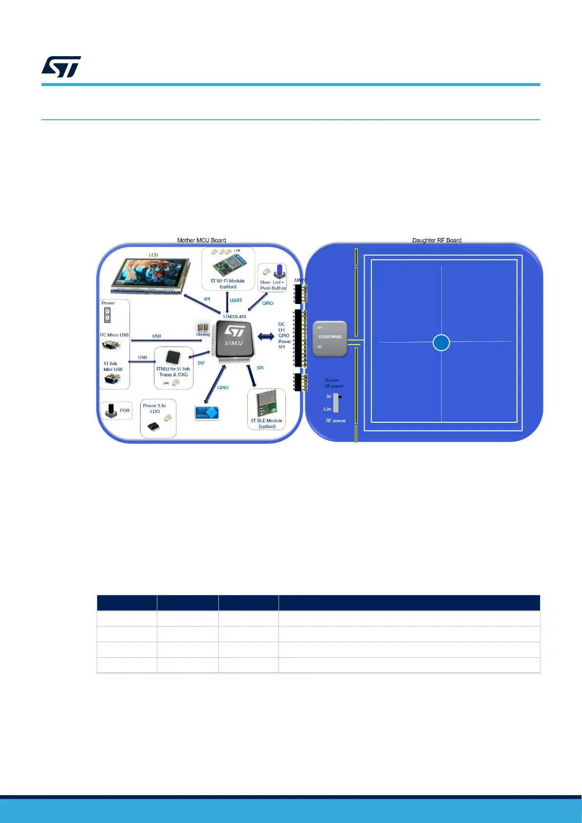
The STM32 MCU firmware controls the ST25R3916B via the extension connectors.
The 5 V supply of the USB bus powers both boards. An LDO converts this voltage down to 3.3 V to supply the
microcontroller and the ST25R3916B.
For the reader expansion board, you can select a 3.3 or 5 V RF powering. A green LED close to the motherboard
micro-USB plug indicates when the board is powered.
Figure 2. Hardware connection
2.1 Main board hardware
The STEVAL-25R3916B main board embeds a 32-bit microcontroller of the STM32L476 series, which is based on
the Arm Cortex-M4 high-performance CPU with FPU. This board is powered through the USB bus. It includes:
• an ST-LINK in-circuit debugger and programmer for STM32 microcontrollers
• push buttons (reset and user)
• a mini-USB debug connector
• a user-dedicated micro-USB connector
• support for ST NFC tag
Table 1. Powering options
Reference
Connector Position Description
1 JP13 Closed 1-2 Card powered by USB
2 JP14 Closed 2-3 Card powered by micro-USB
3 JP15 Open STEVAL-25R3916B board powering (specific feature)
4 JP16 Open Card powered by an external source
UM3033
Hardware overview
UM3033 - Rev 1
page 3/34
 Loading...


