Table 2. Jumper default configuration
Connector Position Description
JP2
Closed 1-2
ST-LINK UART debug featuresJP3
JP10
JP13 Card powered by USB
JP14 Closed 2-3 Card powered by micro-USB
JP16 Closed 1-2 Board powering specific feature
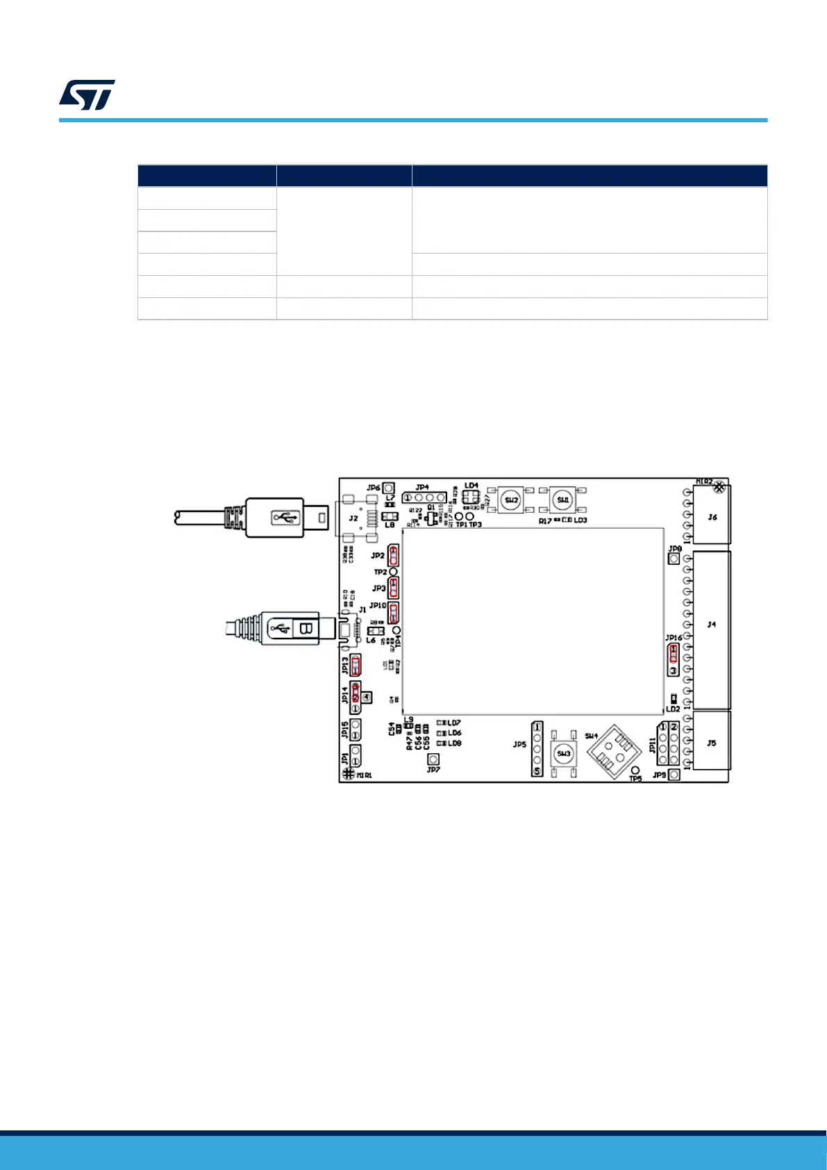
2.1.2 Software development configuration
This section describes the software development configuration for the main board. It also describes the USB
connection when using the embedded ST-LINK.
The J1 micro-USB connector powers the STEVAL-25R3916B.
The J2 mini-USB allows exchanging data between the board and the computer.
Figure 6. Software development configuration
2.2 Expansion board hardware
The STEVAL-25R3916B reader expansion board embeds:
• ST25R3916B
• an antenna, with its own tuning circuit, etched on the PCB
• a switch to select 3.3 V or 5 V RF powering
The ST25R3916B is directly connected to the filtered 5 V USB supply.
There are additional supply filtering components close to the NFC/HF reader IC. All the decoupling capacitors
have been placed as close as possible to the ST25R3916B.
To connect another reader PCB via SPI, remove the serial resistors and use CN100. By default, the SPI is the
firmware and hardware access bus.
Use the I²C bus, instead, by changing J200, J201, J202, J203, J204, and J205.
J206 allows bypassing the internal V
DD_RF
/V
DD_AM
regulators to supply an output current higher than 350 mA.
UM3033
Expansion board hardware
UM3033 - Rev 1
page 6/34
 Loading...


