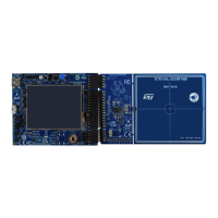
Figure 4. STEVAL-25R3916B main board layout (bottom view)
1. STM32L476 MCU
2. Test points for external connections
3. Room for Wi-Fi module
4. Regulator
5. STM32 ST-LINK
6. Room for Bluetooth® Low Energy module
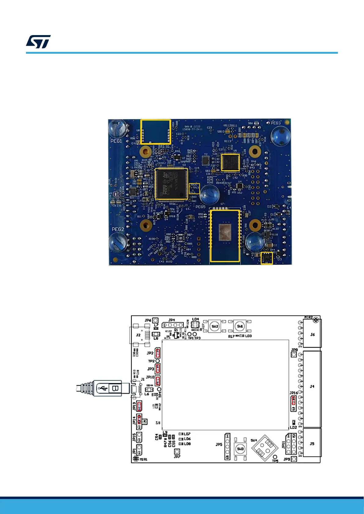
2.1.1 Jumper default configuration
The STEVAL-25R3916B jumpers are configured by default to power the kit through the micro-USB connector.
Figure 5. Jumper default configuration
UM3033
Main board hardware
UM3033 - Rev 1
page 5/34
 Loading...


