Hardware layout and configuration UM2206
20/55 UM2206 Rev 3
should be on pins 3 and 4 to select 5V_VIN power source on silkscreen of JP5. In that case
the DC power comes from the power supply through the Arduino Uno V3 battery shield
(compatible
with Adafruit PowerBoost 500 shield).
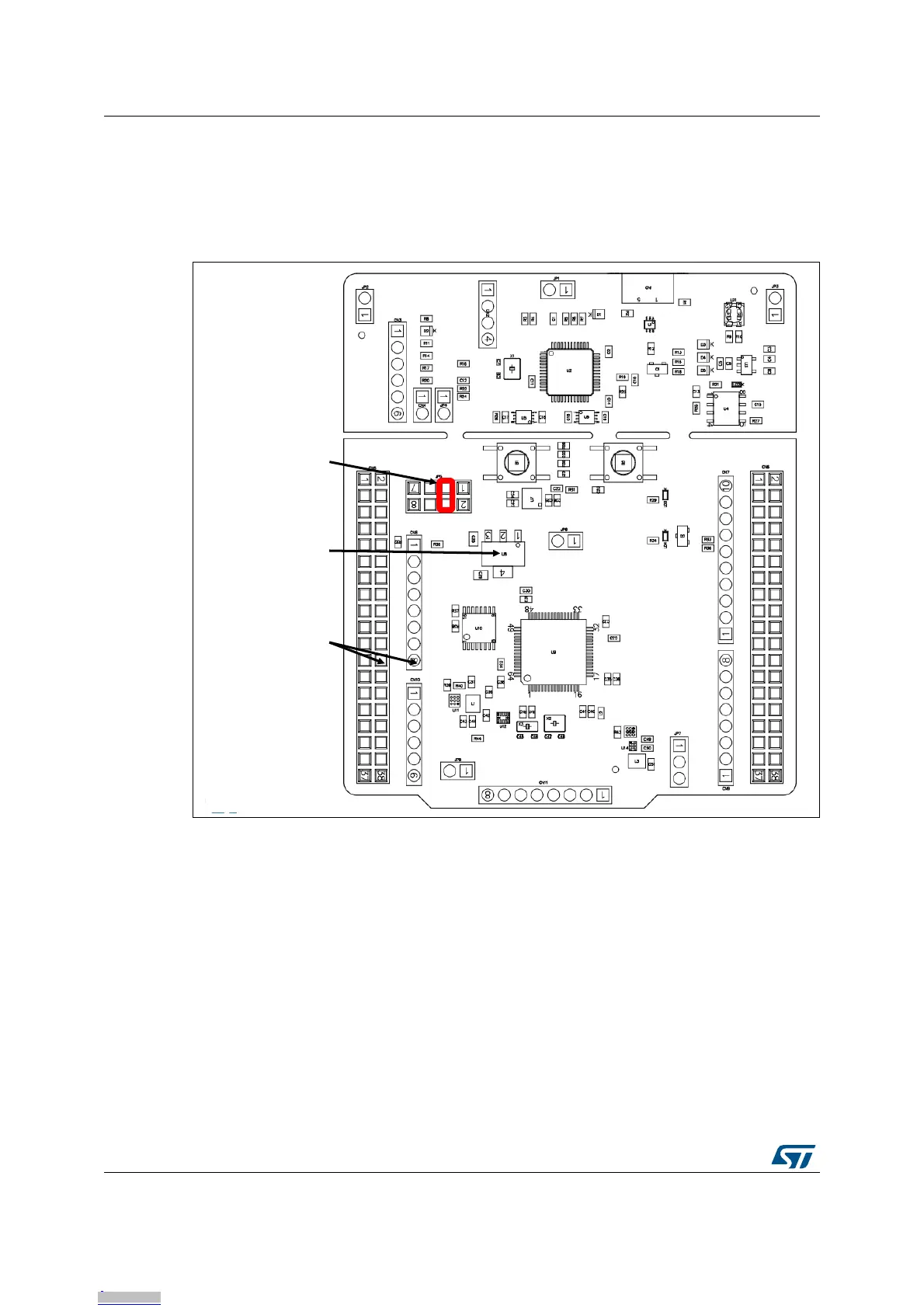
5V_VIN configuration: jumper JP5[3-4] should be connected as showed in Figure 11.
Figure 11. JP5[3-4]: 5V_VIN power source
E5V is the DC power coming from external (5V DC power from ST morpho connector CN5
pin 6). In this case JP5 jumper should be on pins 5 and 6 to select E5V power source on
silkscreen of JP5.
E5V configuration: Jumper JP5[5-6] should be connected as showed in Figure 12.
VIN 7-12V
CN8 pin 8
CN5 pin 24
U8 LDO
VIN 7-12V
VOUT 5V
PWR connector:
JP5 [3-4] ON
Downloaded from Arrow.com.Downloaded from Arrow.com.Downloaded from Arrow.com.Downloaded from Arrow.com.Downloaded from Arrow.com.Downloaded from Arrow.com.Downloaded from Arrow.com.Downloaded from Arrow.com.Downloaded from Arrow.com.Downloaded from Arrow.com.Downloaded from Arrow.com.Downloaded from Arrow.com.Downloaded from Arrow.com.Downloaded from Arrow.com.Downloaded from Arrow.com.Downloaded from Arrow.com.Downloaded from Arrow.com.Downloaded from Arrow.com.Downloaded from Arrow.com.Downloaded from Arrow.com.
 Loading...


