UM2324 Rev 2 11/44
UM2324 Hardware layout and configuration
43
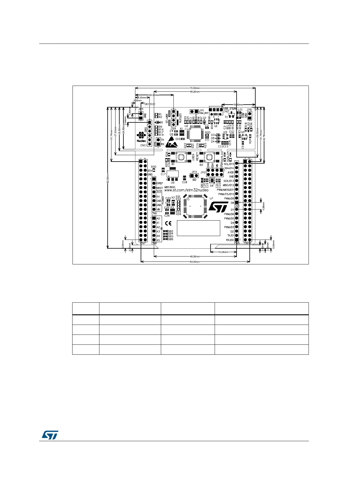
6.1 NUCLEO-G070RB or NUCLEO-G071RB board mechanical
drawing
Figure 5. NUCLEO-G070RB or NUCLEO-G071RB board mechanical drawing
6.2 Default board configuration
6.3 Cut able PCB
The NUCLEO-G070RB or NUCLEO-G071RB board is divided into two parts: ST-Link part
and target MCU part. ST-Link part PCB is cuttable to reduce board size. In this case the rest
target MCU part is only powered by VIN, E5V & 3.3V on morpho connectors CN7 or VIN &
3.3V on Arduino connector CN6. And it is still possible to use ST-Link part to program the
main MCU using wires between CN7 and SWD signals available on morpho connectors.
Table 4. Default jump settings
Jumper Definition Default position Comment
CN4 SWD interface ON [1-2] ON[3-4] On-board ST-LINK/V2-1 debugger
JP2 5 V Power selection ON [1-2] 5 V from ST-LINK
JP1 STLK Reset OFF No STLK Reset
JP3 I
DD
measurement ON STM32 VDD current measurement

 Loading...

