Hardware layout and configuration UM2324
24/44 UM2324 Rev 2
6.11 Push buttons
• B1 USER: User and Wake-Up button connected to the I/O PC13 (Pin 3) of the STM32
Microcontroller.
• B2 RESET: Pushbutton connected to NRST is used to RESET the STM32
Microcontroller.
The blue and black plastic hats placed on these pushbuttons are removable if necessary
when a shield or an application board is plugged on top of Nucleo. This avoids pressure on
the buttons and consequently a possible permanent Target MCU RESET.
6.12 I
DD
measurement
Jumper JP3, labeled IDD, allows the consumption of STM32 Microcontroller to be measured
by removing the jumper and connecting an ammeter.
• Jumper on: STM32 Microcontroller is powered (default).
• Jumper off: an ammeter must be connected to measure STM32 microcontroller
current. If there is no ammeter, STM32 microcontroller is not powered.
6.13 Jumper configuration
The default jumper positions are showed in Table 4: Default jumper settings. Table 9
describes the other available jumper settings.
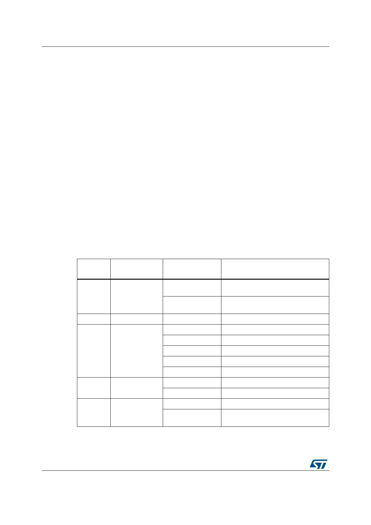
Table 9. Jumper configuration
Jumper /
CN
Function State
(1)
1. Default jumper state is shown in bold.
Comment
CN4
T_SWCLK
T_SWDIO
ON [1-2] ON [3-4]
ST-LINK/V2-1 enable for on-board
MCU debugger
OFF [1-2] OFF [3-4]
ST-LINK/V2-1 functions enabled for
external CN2 connector
JP4/JP5 GND ON GND probe
JP2
5 V Power
selection
ON [1-2] 5 V from ST-LINK
ON [3-4] 5 V from VIN 7 V to 12 V
ON [5-6] 5 V from E5V
ON [7-8] 5 V from USB_CHG
OFF No 5 V power
JP1 STLK Reset
ON [1-2] STLK Reset
OFF No STLK Reset
JP3 I
DD
measurement
ON [1-2] VDD = 3.3 V
OFF
To connect external source (ULPBench
probe as an example)
 Loading...


