DocID025097 Rev 1 25/39
UM1658 Connecting modules on the prototyping board
38
5 Connecting modules on the prototyping board
This section gives some examples of how to connect ready-to-use modules available from
different manufacturers to the STM32F030 Value Line Discovery kit via the prototyping
board included in the kit.
Software examples, based on the connections described below, are available at
www.st.com/stm32f0-discovery.
5.1 Mikroelektronica accessory boards
Mikroelektronika, http://www.mikroe.com, has specified two standard connectors for their
accessory boards, named mikroBUS™ (http://www.mikroe.com/mikrobus_specs.pdf) and
IDC10.
MikroBUS™ is a 16-pin connector to connect accessory boards very quickly and easily to a
microcontroller board through SPI, USART or I
2
C communications, along with additional
pins such as Analog Input, PWM and Interrupt.
The set of mikroElektronika boards compatible with mikroBUS™ is called “Click boards”.
IDC10 is a 10-pin connector to connect the general purpose I/O of an MCU to other
accessory boards.
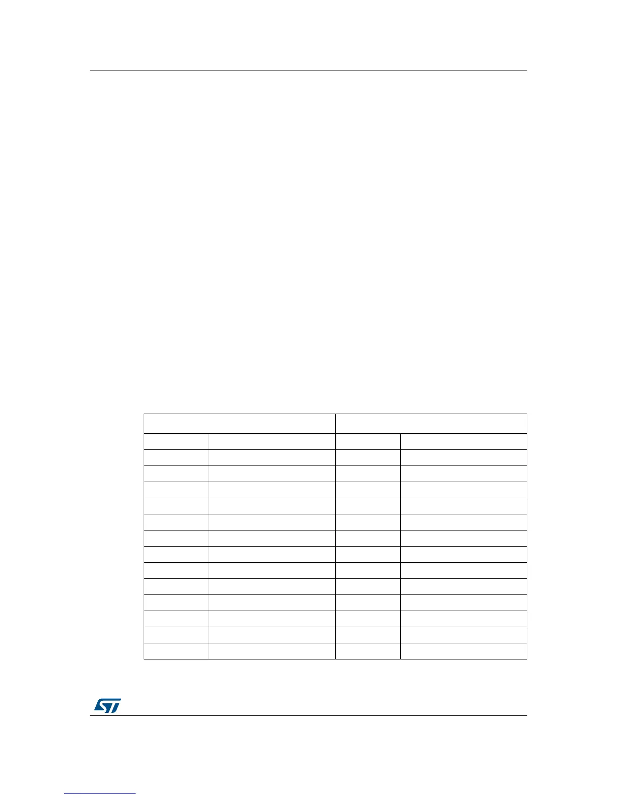
The tables below are one solution for connecting mikroBUS™ and IDC boards to the
32F0308DISCOVERY; this solution used in the different examples is available at
www.st.com/stm32f0-discovery.
Table 6. Connecting using mikroBUS™
Mikroelektronica mikroBUS™ 32F0308DISCOVERY
Pin Description Pin Description
AN Analog pin PA4 DAC1_OUT
RST Reset pin PB13 GPIO OUTPUT (5V tolerant)
CS SPI Chip Select line PA11 GPIO OUTPUT (5V tolerant)
SCK SPI Clock line PB3 SPI1_SCK
MISO SPI Slave Output line PB4 SPI1_MISO
MOSI SPI Slave Input line PB5 SPI1_MOSI
PWM PWM output line PA8 TIM1_CH1
INT Hardware Interrupt line PB12 GPIO INPUT EXTI (5V tolerant)
RX UART Receive line PA3 USART2_RX
TX UART Transmit line PA2 USART2_TX
SCL I2C Clock line PF6 I2C2_SCL
SDA I2C Data line PF7 I2C2_SDA
5V VCC 5V power line 5V Power line