Hardware layout and configuration UM1907
14/49 DocID027942 Rev 3
• 5V DC power with 500 mA limitation from CN13, the USB OTG FS micro-AB connector
(USB 5V power source on silkscreen of JP1 (usb_fs)).
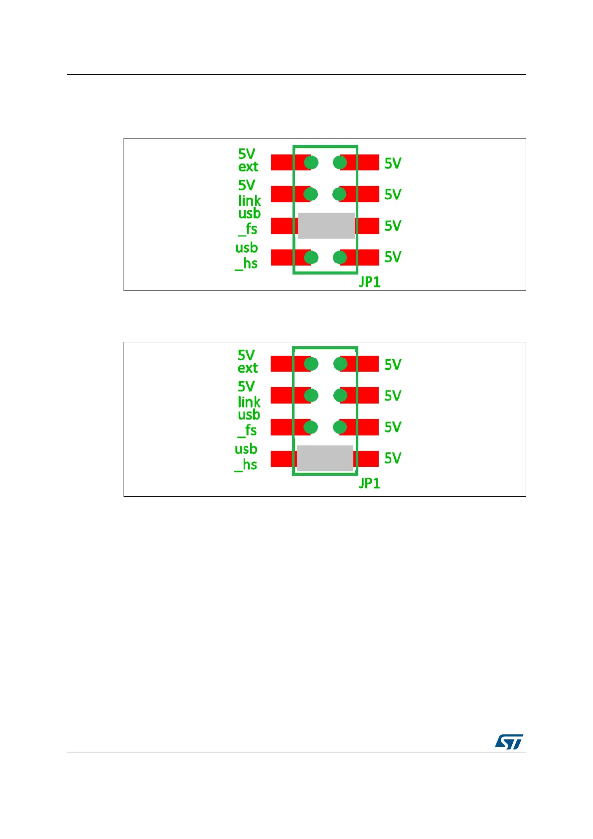
Figure 10. JP1 (usb_fs)
• 5V DC power with 500 mA limitation from CN12, the USB OTG HS micro-AB connector
(USB 5V power source on silkscreen of JP1 (usb_hs)).
Figure 11. JP1 (usb_hs)
6.3 Programming/debugging when the power supply is not from
ST-LINK (5V link)
It is mandatory to power the board first using JP1 (5V ext) or (usb_hs) or (usb_fs), then
connecting the USB cable to the PC. Proceeding this way ensures that the enumeration
succeeds thanks to the external power source.
The following power sequence procedure must be respected:
1. Connect the jumper JP1 on (5V ext) or (usb_hs) or (usb_fs)
2. Connect the external power source to JP2 or CN6 or CN12 or CN13
3. Check the red LED LD2 is turned ON
4. Connect the PC to USB connector CN14
If this order is not respected, the board may be powered by VBUS first from ST-LINK, and
the following risks may be encountered: